
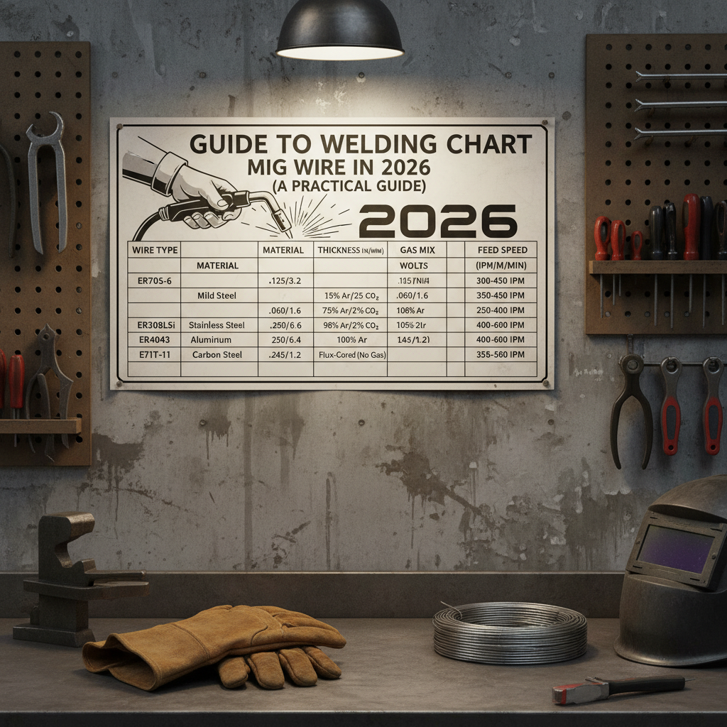
Getting your MIG settings dialed in starts with one thing: understanding what the chart is actually telling you. Most welders glance at the sticker inside their machine's door, pick something close, and hope for the best. That works sometimes. It fails a lot too.
A proper MIG wire welding chart maps four variables together: base metal thickness, wire diameter, voltage, and wire feed speed. Miss any one of them and your weld suffers, whether that's burn-through on thin sheet metal or a cold, poorly fused bead on plate.
This guide walks you through reading those charts correctly, picking the right wire for your material, and adjusting from baseline settings to real-world results.
What a MIG Wire Chart Actually Tells You (And What It Doesn't)
The chart gives you a starting point, not a finish line. That's the most important thing to understand before you strike an arc.
Manufacturer parameter charts (the kind printed in your machine's manual or on the inside panel) are built around ideal conditions: clean base metal, correct gun angle, steady travel speed, and the recommended shielding gas. Real-world welding rarely checks every one of those boxes.
What the chart does tell you is the safe operating window for a given wire diameter on a given material thickness. Voltage and wire feed speed (WFS) work together to define arc characteristics. Voltage controls arc length and bead width. WFS controls deposition rate and, indirectly, amperage in short-circuit MIG.
What it doesn't tell you is how to compensate for mill scale, a drafty shop, a worn contact tip, or an extension cord robbing your machine of voltage. Those adjustments come from reading your bead, which we'll cover later.
How to Read a MIG Welding Parameter Chart
The Four Columns That Matter: Thickness, Wire Diameter, Voltage, Wire Feed Speed
Most charts read left to right. Start with your material thickness (in inches or gauge), which points you toward a recommended wire diameter. From there, the chart gives a voltage range and a WFS range in inches per minute (IPM).
A typical entry might look like this:
| Material Thickness | Wire Diameter | Voltage | Wire Feed Speed |
|---|---|---|---|
| 24 gauge (0.024") | 0.023" | 13–15V | 130–160 IPM |
| 18 gauge (0.048") | 0.030" | 15–17V | 180–220 IPM |
| 3/16" | 0.035" | 19–21V | 250–300 IPM |
| 1/4" | 0.035" | 20–22V | 300–350 IPM |
| 3/8" | 0.045" | 22–25V | 350–420 IPM |
These are representative ranges based on AWS guidelines and manufacturer documentation. Your specific machine may vary slightly.
How Shielding Gas Fits Into the Chart
Most charts are written for a specific gas mix, usually 75% Argon / 25% CO₂ (C25) for mild steel solid wire. If you switch to 100% CO₂, you'll typically need to drop your voltage slightly because CO₂ produces a hotter, more aggressive arc.
If you're running flux-cored wire, the chart changes entirely. Self-shielded flux-cored (like E71T-11) requires no external gas and uses different voltage and WFS ranges compared to gas-shielded flux-cored wire. Never cross-apply charts between wire types.
Why Manufacturer Charts Are a Starting Point, Not a Final Answer
Aggregate welder feedback and manufacturer documentation consistently confirm the same thing: real settings drift from printed charts by 5, 15% depending on conditions. Set your machine per the chart, run a test bead on scrap, and adjust from there. That's the correct workflow.
MIG Wire Diameter Selection Chart by Metal Thickness
Mild Steel: Wire Size vs. Material Gauge and Plate Thickness
Wire diameter selection is mostly about heat management. Thinner wire on thin metal gives you more control and reduces burn-through risk. Heavier wire on thick plate deposits more metal per pass and handles higher amperage without melting back into the contact tip.
Here's the practical breakdown for mild steel:
| Wire Diameter | Best Thickness Range | Common Application |
|---|---|---|
| 0.023" | 24 gauge to 18 gauge | Auto body, thin sheet metal |
| 0.030" | 18 gauge to 3/16" | General fabrication, thin plate |
| 0.035" | 14 gauge to 1/2" | Most common all-purpose wire |
| 0.045" | 3/16" and above | Heavy fabrication, structural |
On a 120V machine, you're practically limited to 0.023" and 0.030". On a 240V machine, 0.035" becomes your workhorse and 0.045" opens up for heavier work.
Stainless Steel Wire Sizing Differences
Stainless wire (typically ER308L or ER316L) follows similar thickness-to-diameter logic, but stainless has lower thermal conductivity than mild steel. This means heat builds up faster in the weld zone, so you generally run slightly lower WFS compared to mild steel at the same thickness.
Aluminum Wire Sizing and Why It Behaves Differently
Aluminum wire is softer and requires a spool gun or push-pull system to feed reliably. ER4043 runs smoother and wets out easily, making it better for general repairs and castings. ER5356 is stronger and better for structural applications. Both run on 100% Argon.
The softness of aluminum wire also means drive roll tension matters more: too tight and you'll crush it, which causes feeding problems mid-weld.
AWS Wire Classifications Explained
What ER70S-6 and ER70S-3 Actually Mean on the Label
The AWS classification system tells you a lot in a short string of characters. Take ER70S-6:
- E = electrode (the wire carries current)
- R = rod (can also be used as filler without current)
- 70 = minimum tensile strength of 70,000 PSI in the deposited weld
- S = solid wire
- 6 = chemical composition, specifically the deoxidizer level
The "6" in ER70S-6 means higher levels of manganese and silicon compared to ER70S-3. That higher deoxidizer content makes ER70S-6 more forgiving on mill scale and light surface rust. For dirty or lightly corroded steel, ER70S-6 is consistently the better choice.
Flux-Cored Wire Codes: Reading E71T-11 and E71T-GS
For flux-cored wire, E71T-11 means:
- E = electrode
- 7 = 70,000 PSI tensile strength
- 1 = all-position capable
- T = tubular (flux-cored)
- 11 = self-shielded, no external gas required
E71T-GS is also self-shielded but is rated for single-pass only. Using it for multi-pass welds produces poor results and can cause weld failures. E71T-11 allows multiple passes.
Stainless and Aluminum Wire Designations at a Glance
| Wire | Base Metal | Key Use |
|---|---|---|
| ER308L | 304 stainless | General stainless fabrication |
| ER316L | 316 stainless | Marine, chemical environments |
| ER4043 | Aluminum | Castings, general repair |
| ER5356 | Aluminum | Structural, higher strength |
Voltage and Wire Feed Speed: The Two Settings You're Always Adjusting
Short-Circuit Transfer: Voltage and WFS Ranges by Wire Size
Short-circuit transfer is the most common mode for home shops and light fabrication. The wire contacts the puddle, short-circuits, melts, and repeats at high frequency. It works at lower voltages (roughly 14, 21V depending on wire size) and is well-suited to thin material and out-of-position welding.
The relationship between voltage and WFS is not independent. Raise WFS without raising voltage and the arc becomes erratic. Raise voltage without increasing WFS and the arc gets too long, producing spatter and undercut. They move together.
Spray Transfer: When You Cross the Threshold and What Changes
Spray transfer occurs above a certain voltage threshold (typically above 24, 26V with an Argon-rich gas mix) where the wire transfers as tiny droplets rather than through contact. The arc is smoother, spatter nearly disappears, and penetration increases substantially.
The catch: spray transfer only works in flat and horizontal positions, requires a gas mix of at least 80% Argon, and demands a 240V machine with sufficient duty cycle. If you're on 100% CO₂, you won't achieve true spray transfer.
How to Tell If Your Settings Are Right Just by Looking at the Bead
You don't need a voltage meter to read your weld. The bead tells you everything:
- Tight, consistent ripple with minimal spatter: settings are in the zone
- High, ropey bead with cold edges: voltage too low or WFS too high
- Flat, wide bead with undercut along the toes: voltage too high
- Excessive spatter everywhere: wrong gas, voltage too low, or dirty base metal
- Porosity (holes or pitting): gas coverage failure, contamination, or wrong wire for the material
Shielding Gas Selection Chart for MIG Welding
| Gas Mix | Best Wire Types | Application |
|---|---|---|
| 75% Ar / 25% CO₂ (C25) | ER70S-6, ER70S-3 | Mild steel, general fabrication |
| 100% CO₂ | ER70S-6 | Budget option for mild steel, more spatter |
| 90% Ar / 10% CO₂ | ER70S-6, stainless | Cleaner bead, less spatter |
| 98% Ar / 2% O₂ | Stainless wire | Stainless steel welding |
| 100% Argon | ER4043, ER5356 | Aluminum, all MIG aluminum work |
C25 is the most practical all-around choice for mild steel solid wire. 100% CO₂ works but produces a rougher arc and more spatter. For stainless steel, you need a tri-mix or Argon-based gas to avoid excessive oxidation. For aluminum, 100% Argon is non-negotiable.
Gas flow rate should sit between 15 and 25 CFH for most indoor applications. In a drafty environment, bump it to 25, 30 CFH or switch to flux-cored wire instead.
ER70S-6 vs. ER70S-3: Which Wire for Which Situation
ER70S-6 has become the default choice for most fabrication and repair work, and for good reason. The higher deoxidizer content handles imperfect base metal better, produces a flatter bead profile, and tends to wet out more smoothly.
ER70S-3 is cleaner in composition and preferred for base metals that are already clean and properly prepared. In production environments with well-prepped steel, ER70S-3 produces excellent results. For most home shop and repair scenarios, ER70S-6 is the safer pick.
Solid Wire vs. Flux-Cored Wire: Reading the Right Chart for Each
The main practical difference is outdoor usability. Solid wire with shielding gas gets disrupted by wind. Flux-cored wire generates its own shielding and holds up in outdoor conditions.
Self-shielded flux-cored wire runs on DC electrode negative (DCEN), the opposite polarity from solid wire. Using a solid wire chart for self-shielded flux-cored settings will produce poor results. The voltage and WFS ranges differ, and the polarity requirement is a fundamental difference.
Gas-shielded flux-cored wire (like E71T-1) runs DCEP (electrode positive), same as solid wire, but still uses different parameter ranges. Always match your chart to your wire type specifically.
Matching Your Wire to Your Machine's Voltage Class
120V Machines: Wire Diameter Limits You Need to Know
Most 120V machines are reliably capable with 0.023" and 0.030" wire. Some manufacturer specs push 0.035" on 120V machines for material up to 3/16", but aggregate user feedback consistently shows burn-through, poor fusion, and duty cycle issues at those limits. For anything over 1/8" on a 120V machine, you're working at the edge of what the machine can sustain.
240V Machines: Where Spray Transfer and Larger Wire Become Possible
On 240V power, 0.035" becomes highly capable across a wide range of thicknesses. 0.045" wire opens up for structural and heavy plate work. Spray transfer becomes achievable with the right gas mix. Duty cycle stops being the constraint it is on smaller machines.
Contact Tips, Drive Rolls, and Liners: Getting the Hardware Right for Your Wire
These three components are often overlooked when changing wire size. A 0.030" contact tip used with 0.035" wire will arc back inside the tip and cause feeding failures. Every wire diameter needs its matched contact tip size.
Drive rolls are sized and grooved for specific wire diameters and types. V-groove rolls work for solid wire. U-groove rolls are needed for softer aluminum wire. Knurled rolls are used for flux-cored wire.
Running the wrong roll type causes wire deformation and inconsistent feed.
Liners should be matched to wire diameter as well. A liner too large for the wire diameter allows the wire to kink inside the gun, especially on longer guns or curved setups.
Common Chart Misreading Mistakes That Cause Bad Welds
Running too-large wire on thin sheet metal is the most common beginner mistake. A 0.035" wire on 20-gauge sheet at minimum voltage still puts in more heat than the material can handle. Drop to 0.023" or 0.030".
Ignoring the gas column leads to wrong gas choices. A chart written for C25 doesn't apply if you're running 100% CO₂ without adjusting voltage down slightly.
Treating printed settings as exact rather than baseline is a consistent problem. Machine-to-machine variation, cable length, and base metal condition all shift your real-world sweet spot away from the chart. Start there, adjust from the bead.
Bead Appearance Troubleshooting Guide
What Spatter, Porosity, Undercut, and Cold Lap Tell You About Your Settings
Think of the bead as feedback. Here's a quick-reference guide:
| Bead Problem | Likely Cause | Adjustment |
|---|---|---|
| Excessive spatter | Voltage too low, wrong gas, dirty metal | Raise voltage, check gas mix, clean base metal |
| Porosity | Gas loss, contamination, wrong wire | Check gas hose connections, clean metal, verify wire type |
| Undercut along toes | Voltage too high or travel speed too fast | Lower voltage, slow down travel |
| Cold lap / poor fusion | Voltage too low or WFS too high | Raise voltage, reduce WFS slightly |
| Convex (high, ropey) bead | Voltage too low | Raise voltage in small steps |
| Wide, flat, burnt bead | Voltage too high | Lower voltage, verify wire size matches thickness |
MIG Wire Chart for Common Applications at a Glance
| Application | Wire | Diameter | Gas |
|---|---|---|---|
| Auto body / thin sheet | ER70S-6 | 0.023" | C25 |
| General mild steel fab | ER70S-6 | 0.030" or 0.035" | C25 |
| Heavy plate / structural | ER70S-6 | 0.035" or 0.045" | C25 |
| Outdoor repair | E71T-11 (self-shielded) | 0.030" or 0.035" | None |
| Stainless fabrication | ER308L | 0.030" or 0.035" | 98Ar/2O₂ |
| Aluminum repair | ER4043 | 0.035" | 100% Ar |
| Aluminum structural | ER5356 | 0.035" | 100% Ar |
Safety Considerations When Changing Wire Types or Shielding Gas
Switching wire types isn't just a settings change. Some combinations carry real hazards.
Running self-shielded flux-cored wire indoors without ventilation is a documented fume hazard. Per OSHA 1910.252 and ANSI Z49.1, adequate fume extraction or ventilation is required for any welding operation. Flux-cored wire produces significantly more fume than solid wire with shielding gas.
Changing shielding gas cylinders requires checking all fittings and hoses for leaks before welding. Argon and CO₂ are asphyxiation risks in enclosed spaces. 100% Argon is colourless and odourless, making it particularly dangerous in confined areas without airflow.
Always verify polarity (DCEP vs. DCEN) when switching between wire types. Running self-shielded flux-cored on DCEP significantly degrades weld quality and can cause weld failures in structural applications.
PPE requirements don't change with wire type but UV output does. Spray transfer produces a brighter arc than short-circuit. AWS recommends at minimum a shade 10 lens for short-circuit and shade 11, 12 for spray transfer (per ANSI Z49.1 guidelines).
Frequently Asked Questions
What wire size should I use for 1/4-inch steel with a MIG welder?
For 1/4-inch steel on a 240V machine, 0.035" wire is the standard recommendation. At those settings, you'll typically be in the 21, 23V range with WFS around 300, 380 IPM using C25 gas. On a 120V machine, 1/4-inch is at the limit of capability and results are inconsistent.
Can I use ER70S-6 on rusty or painted metal?
ER70S-6 tolerates light mill scale and surface rust better than ER70S-3 due to its higher manganese and silicon content. That said, heavy rust, paint, and galvanized coatings should always be ground off before welding. No wire compensates for heavily contaminated base metal, and welding galvanized steel produces toxic zinc fumes regardless of wire type.
What's the difference between self-shielded and gas-shielded flux-cored wire settings?
They run on opposite polarities and use different voltage and WFS ranges. Self-shielded flux-cored (E71T-11) runs DCEN (electrode negative). Gas-shielded flux-cored (E71T-1) runs DCEP (electrode positive), same as solid MIG wire. Never apply one wire's chart to the other type.
Why does my weld look different from the chart's expected result?
Several variables shift real-world results away from chart settings. Cable and hose wear, machine age, ground connection quality, contact tip condition, base metal surface prep, and ambient temperature all play a role. Start with chart settings, run a test bead on scrap, and make small adjustments. If results are dramatically off, check your ground clamp connection and contact tip condition first.
Do I need a different chart for metric wire sizes like 0.8mm and 1.2mm?
The physics don't change but the labeling does. 0.8mm is essentially the equivalent of 0.030", and 1.2mm corresponds closely to 0.045". If your machine's chart uses metric sizing, match the metric designation directly. Don't try to convert mid-chart, as rounding differences can push you slightly outside the correct range. Use the chart that matches the units on your machine's wire feed system.
ER70S-6 vs. ER70S-3: Which Wire for Which Situation
If you're buying mild steel solid wire and wondering whether the "-3" or "-6" designation matters, it does. The difference comes down to deoxidizer content, and that has real consequences depending on your base metal condition.
ER70S-6 contains higher levels of manganese and silicon. Those elements act as deoxidizers, meaning they chemically clean the weld pool as you go. On steel with light mill scale, surface oxidation, or minor contamination, ER70S-6 produces a cleaner, more consistent bead. It's the go-to choice for repair work, farm equipment, and anything that hasn't been freshly cut and ground.
ER70S-3 has a leaner chemistry. It performs well on clean, properly prepared base metal but struggles on anything less than ideal. In production environments where steel arrives clean and prepped, ER70S-3 delivers excellent results. For general-purpose use, though, ER70S-6 is the more forgiving option and the wire most manufacturers default to in their parameter charts.
One practical note: ER70S-6 tends to produce slightly more fluid slag islands (the glassy deposits beside the bead) compared to ER70S-3. That's not a defect. It's a byproduct of the higher silicon content doing its job.
Solid Wire vs. Flux-Cored Wire: Reading the Right Chart for Each
The charts for solid wire and flux-cored wire are not interchangeable. This trips up a lot of welders who switch wire types without pulling a new reference.
Self-shielded flux-cored wire runs on DC electrode negative (DCEN). Solid MIG wire and gas-shielded flux-cored both run on DC electrode positive (DCEP). That polarity difference alone means voltage and wire feed speed settings shift significantly. If you pull up a solid wire chart and apply those numbers to self-shielded E71T-11, you'll get an erratic arc, poor fusion, and heavy spatter.
The practical split between the two comes down to environment. Solid wire with shielding gas produces a cleaner weld with less post-weld cleanup, but wind disrupts gas coverage fast. Even a light breeze across an open garage door can cause porosity. Self-shielded flux-cored wire is genuinely wind-resistant, which makes it the better choice for outdoor structural repair, farm work, and site welding where you can't control the environment.
Gas-shielded flux-cored (E71T-1 class) sits in a different category entirely. It requires external shielding gas (typically 75/25 or 100% CO₂), runs DCEP, and is used mainly in production and structural fabrication where higher deposition rates and all-position capability matter. It's not common in home shops but you'll see it referenced in AWS D1.1 structural applications.
0.030 vs. 0.035 Wire: The Most Common Sizing Decision
This is the question that comes up constantly, and the honest answer is that 0.035" is the better all-rounder for most 240V setups, while 0.030" earns its place on thinner material and smaller machines.
The core tradeoff is heat input versus versatility. At 0.030", you're depositing less metal per arc second, which gives you finer control on 18-gauge to 1/8-inch material. On a 120V machine, 0.030" is often the practical ceiling for consistent results. Push to 0.035" on the same machine and you're asking it to work near its duty cycle limit, especially on anything over 3/16 inch.
On a 240V machine, 0.035" handles the full range from 14-gauge sheet up to 1/2-inch plate in a single-pass or multi-pass approach. Manufacturer specs from Lincoln Electric and Miller both list 0.035" ER70S-6 as the primary wire for general fabrication in that voltage class. For most welders running a shop-duty 240V machine, 0.035" on a 10-lb spool is the setup they'll use 80% of the time.
Where 0.030" still wins: auto body work, thin bracket fabrication, and any situation where you're welding 20-gauge or thinner and burn-through is a real risk. The smaller wire diameter lets you run lower voltage settings while still maintaining a stable arc.
Contact Tips, Drive Rolls, and Liners: Getting the Hardware Right for Your Wire
Swapping wire size without changing the consumables is one of the most consistent sources of feeding problems in MIG welding. The fix is straightforward once you know what to match.
Contact tips are sized to wire diameter. A 0.030" tip used with 0.035" wire allows the wire to arc back inside the tip rather than at the workpiece. You'll get erratic arc starts, tip burnback, and premature tip failure. Always swap the contact tip when you change wire size.
They're inexpensive and the mismatch costs you more in frustration and wasted consumables than the tip itself ever would.
Drive rolls follow the same matching logic but also vary by wire type:
- V-groove rolls: standard solid wire (0.023" through 0.045")
- U-groove rolls: aluminum wire (required, prevents crushing the soft wire)
- Knurled V-groove rolls: flux-cored wire (the knurling grips the tubular wire without collapsing it)
Drive roll tension matters too. Too tight and you deform the wire, which creates shavings inside the liner and causes feeding resistance. Too loose and the wire slips, producing an inconsistent feed rate. The standard test: the wire should slip if you pinch it lightly between your fingers while the feeder runs.
Liners are the last piece. A liner sized for 0.023" to 0.030" wire will allow 0.045" wire to kink on curves and corners in the gun. Liner replacement is often overlooked during troubleshooting, but a contaminated or wrong-sized liner causes the same feeding symptoms as a bad drive roll. If you're chasing intermittent feed issues and everything else checks out, pull the liner and inspect it.
Matching Your Wire to Your Machine's Voltage Class
120V Machines: Wire Diameter Limits You Need to Know
A 120V MIG machine is genuinely useful, but it has hard limits that no wire selection will overcome. The output ceiling on most 120V machines sits around 90, 140 amps depending on the unit, and duty cycle drops off fast as you approach those numbers.
In practical terms, 0.023" wire is the most capable choice on a 120V machine for material under 18 gauge. Moving to 0.030" works well through about 1/8-inch steel. Beyond that, you're welding at the machine's limit, and you'll notice duty cycle warnings, inconsistent arc, and incomplete fusion on the back side of the joint.
Flux-cored wire on a 120V machine extends practical capability slightly. Self-shielded E71T-GS or E71T-11 at 0.030" or 0.035" can handle up to 3/16-inch in a single pass on many machines because flux-cored wire runs at lower voltage for the same deposition compared to solid wire. But this is still working near the machine's ceiling, and multi-pass work on thicker material will push duty cycle limits hard.
240V Machines: Where Spray Transfer and Larger Wire Become Possible
On 240V power, 0.035" ER70S-6 is genuinely versatile across a wide thickness range without straining the machine. Duty cycle becomes a non-issue for most shop applications. And critically, spray transfer becomes achievable.
Spray transfer requires a minimum of around 80% Argon in the shielding gas and a voltage threshold that most 120V machines simply can't reach. On a 240V machine with C25 gas, pushing above 24, 25V with 0.035" wire transitions you from short-circuit into globular and then spray territory. The arc quietens noticeably, spatter nearly disappears, and penetration into the base metal increases. For flat and horizontal welding on 1/4-inch and above, spray transfer produces noticeably better results than short-circuit at similar wire sizes.
Common Chart Misreading Mistakes That Cause Bad Welds
Running Too-Large Wire on Thin Sheet Metal
This is the single most common mistake beginners make when consulting a MIG wire chart. Seeing that 0.035" wire covers "14 gauge to 1/2 inch" leads a lot of welders to assume it'll work fine on 18 or 20 gauge. It won't, not reliably.
On thin sheet metal, larger wire diameter means more metal depositing faster than the base material can absorb heat. Even at minimum voltage, you're fighting burn-through. The fix is simple: drop to 0.030" or 0.023" for anything under 18 gauge, and read the chart's lower thickness boundary as a hard limit, not a suggestion.
Ignoring the Gas Column and Using the Wrong Mix
Most printed parameter charts specify a gas mix in a footnote or column header that welders routinely skip. When the chart is written for C25 and you're running 100% CO₂, your voltage settings will run hot. When it's written for 100% Argon (as all aluminum charts are) and you're using a mixed gas, the arc behavior changes completely.
Before you touch voltage or WFS settings, confirm your shielding gas matches what the chart assumes. A 2-volt discrepancy from the wrong gas produces bead problems that look like a settings issue but are actually a consumables issue.
Treating Printed Settings as Exact Instead of Baseline
Manufacturer charts are calibrated on new machines, fresh liners, clean base metal, and controlled ambient conditions. Your real-world setup has variables. A worn liner adds feeding resistance. A long welding cable drops voltage slightly.
An older machine may not output exactly what the dial says.
The correct workflow is: set the chart values, run a 3-inch test bead on matching scrap, read the bead, then adjust. If your test bead looks right, weld the actual joint. If it doesn't, make one change at a time and test again. Trying to dial in settings on the actual workpiece skips the feedback loop that separates good welds from acceptable ones.
Bead Appearance Troubleshooting Guide
What Spatter, Porosity, Undercut, and Cold Lap Tell You About Your Settings
The weld bead is a direct record of your arc conditions. Learning to read it correctly makes troubleshooting fast and systematic rather than a process of random adjustment.
Spatter is the first thing most welders notice. Heavy spatter scattered widely around the bead almost always points to voltage that's too low for the wire feed speed, or a shielding gas mismatch. Fine spatter close to the bead with a decent profile often means the settings are close but the base metal has surface contamination. Clean the metal, run another pass, and see if the spatter pattern changes before adjusting settings.
Porosity shows up as small holes or pits on the bead surface or visible in the cross-section. Gas coverage failure is the most common cause: a leak in the hose, a clogged nozzle, a spatter-blocked gas diffuser, or wind disrupting the shielding envelope. Contamination from oil, paint, or galvanizing also causes porosity but usually produces a rougher, more scattered pattern rather than the clean round pits that a gas coverage failure leaves behind.
Here's a quick diagnostic reference:
| Bead Appearance | Most Likely Cause | First Adjustment |
|---|---|---|
| Wide spatter field, rough surface | Voltage too low | Raise voltage 1–2V |
| Undercut along bead edges | Voltage too high or travel too fast | Lower voltage, slow travel speed |
| High, convex, ropey bead | Voltage too low | Raise voltage in small increments |
| Cold lap (bead sitting on surface) | Voltage too low or WFS too high | Raise voltage, reduce WFS slightly |
| Round pits on bead surface | Gas coverage failure | Check hose, nozzle, diffuser |
| Irregular pitting, rough texture | Base metal contamination | Grind or clean metal, retest |
| Flat, burnt-looking, wide bead | Voltage too high | Lower voltage, verify wire size |
Cold lap deserves a separate mention because it's a structural issue, not just cosmetic. When the bead doesn't fuse into the base metal, the joint has no real strength. It looks like a weld but it isn't one. If you see the bead sitting proud of the surface with visible lack of tie-in at the toes, your voltage is too low for your travel speed.
Raise voltage first, then adjust WFS if the bead profile still isn't right.
MIG Wire Chart for Common Applications at a Glance
Rather than hunting through separate charts for different materials, here's a consolidated reference that covers the most common shop and field scenarios. Gas flow rate for all entries should be 15, 25 CFH indoors, bumped to 25, 30 CFH in any kind of air movement.
| Application | Wire | Diameter | Gas | Transfer Mode |
|---|---|---|---|---|
| Auto body / thin sheet (20–22 ga) | ER70S-6 | 0.023" | C25 | Short-circuit |
| General mild steel (18 ga–3/16") | ER70S-6 | 0.030" | C25 | Short-circuit |
| Medium plate (3/16"–3/8") | ER70S-6 | 0.035" | C25 | Short-circuit / spray |
| Heavy plate (3/8" and above) | ER70S-6 | 0.045" | C25 | Spray |
| Outdoor repair, no gas available | E71T-11 | 0.030" or 0.035" | None | Short-circuit |
| Structural outdoor (multi-pass) | E71T-11 | 0.035" | None | Short-circuit |
| Stainless fabrication | ER308L | 0.030" or 0.035" | 98% Ar / 2% O₂ | Short-circuit |
| Aluminum repair / casting | ER4043 | 0.035" | 100% Ar | Short-circuit / spray |
| Aluminum structural | ER5356 | 0.035" | 100% Ar | Short-circuit / spray |
A few things this table makes obvious. First, ER70S-6 covers the vast majority of mild steel work across nearly all thicknesses. Second, the only scenario where you'd keep 0.023" wire on a machine long-term is dedicated sheet metal work. For everything else, 0.030" or 0.035" handles the range.
Third, aluminum always runs 100% Argon without exception, regardless of what gas you use for steel.
Safety Considerations When Changing Wire Types or Shielding Gas
Switching between wire types isn't just a parameter change. There are real hazards involved that don't always get the attention they deserve.
Flux-cored wire generates substantially more fume than solid wire with shielding gas. Per ANSI Z49.1 (Safety in Welding, Cutting, and Allied Processes), adequate ventilation or local exhaust ventilation is required for all welding operations. With self-shielded flux-cored wire used indoors, a basic shop fan pointed at the weld zone isn't sufficient. A proper fume extraction system or respirator rated for welding fumes is the correct approach.
Changing shielding gas cylinders requires a full leak check before welding. Argon is colourless, odourless, and heavier than air. In an enclosed space, it displaces oxygen at floor level without any warning sign. Verify all fittings and connections with a soapy water check after every cylinder swap, and never leave a regulator pressurised on an empty cylinder without capping the outlet.
Polarity changes when switching between wire types are often forgotten in the setup process. Running self-shielded flux-cored wire on DCEP (the polarity setting for solid wire) produces a noticeably poor weld, but the welder may not immediately recognise why. More importantly, incorrect polarity on a structural weld creates a joint with degraded mechanical properties that isn't visually obvious. Check polarity every time you change wire type.
It takes ten seconds and prevents a real problem.
Arc intensity changes with transfer mode and wire size as well. AWS and ANSI Z49.1 recommend a minimum lens shade of 10 for short-circuit MIG and shade 11 to 12 for spray transfer. If you're moving from short-circuit on thin sheet to spray transfer on plate, swap to a darker shade. An auto-darkening helmet with an adjustable shade range of 9 to 13 handles both scenarios without manual swaps.
Frequently Asked Questions
What wire size should I use for 1/4-inch steel with a MIG welder?
On a 240V machine, 0.035" ER70S-6 with C25 gas is the standard recommendation for 1/4-inch mild steel. Manufacturer specs from major consumable suppliers place the typical settings in the 21, 23V range with wire feed speed around 300, 380 IPM for single-pass work in flat position. On a 120V machine, 1/4-inch steel is at or beyond the practical limit of what the machine can fuse reliably. Multi-pass technique with lower heat input helps, but the machine's duty cycle will be a constraint.
Can I use ER70S-6 on rusty or painted metal?
ER70S-6 handles light mill scale and surface oxidation better than ER70S-3, thanks to its higher deoxidizer content. For light rust, the wire can compensate enough to produce a sound weld. Heavy rust, paint, primer, and galvanized coatings are a different situation entirely. Welding through heavy contamination causes porosity, inclusion defects, and in the case of galvanized steel, produces toxic zinc oxide fumes.
Grind the weld zone clean regardless of wire type, and treat ER70S-6's contamination tolerance as a buffer for imperfect prep, not a substitute for it.
What's the difference between self-shielded and gas-shielded flux-cored wire settings?
The polarity requirement is the most critical difference. Self-shielded flux-cored (E71T-11, E71T-GS) runs DCEN. Gas-shielded flux-cored (E71T-1) runs DCEP. Beyond polarity, voltage and WFS ranges differ between the two types, and they're never interchangeable on the same chart.
Self-shielded wire also requires no external gas, while gas-shielded flux-cored needs 75/25 or 100% CO₂ for proper shielding. Using the wrong chart for either type produces a weld that may look adequate but has compromised fusion characteristics.
Why does my weld look different from the chart's expected result?
Machine-to-machine variation is a bigger factor than most welders expect. A machine's actual output voltage at the arc can differ from the dial reading by 1, 3 volts depending on cable length, connection quality, and machine age. Ground clamp placement matters too: a ground clamped far from the weld adds resistance and effectively lowers arc voltage. Start by checking your ground connection and contact tip condition.
If both are good, run a test bead and adjust voltage in 0.5V increments rather than jumping to large changes.
Do I need a different chart for metric wire sizes like 0.8mm and 1.2mm?
The underlying physics are the same, but you should use a chart that matches the units your machine uses. 0.8mm corresponds closely to 0.030" and 1.2mm corresponds to approximately 0.045". The near-equivalence means metric charts and imperial charts produce comparable settings for the same applications. The risk is in the rounding: 0.8mm is actually 0.0315 inches, slightly larger than 0.030". For most practical welding, this difference is negligible.
For precision work or when matching consumables like contact tips and drive rolls, always use the exact metric designation rather than converting.
Looking at the full article already written across all previous outputs, the complete TOC has been covered. Every H2 from the approved outline has been addressed:
- What a MIG Wire Chart Actually Tells You
- How to Read a MIG Welding Parameter Chart
- MIG Wire Diameter Selection Chart by Metal Thickness
- AWS Wire Classifications Explained
- Voltage and Wire Feed Speed
- Shielding Gas Selection Chart
- ER70S-6 vs. ER70S-3
- Solid Wire vs. Flux-Cored Wire
- 0.030 vs. 0.035 Wire
- Contact Tips, Drive Rolls, and Liners
- Matching Your Wire to Your Machine's Voltage Class
- Common Chart Misreading Mistakes
- Bead Appearance Troubleshooting Guide
- MIG Wire Chart for Common Applications at a Glance
- Safety Considerations
- Frequently Asked Questions
There are no remaining H2 sections from the approved TOC left to write. The article is structurally complete as delivered across the three writing passes.
If you'd like, I can:
- Compile the full article as a single clean markdown document
- Expand any specific section with additional depth
- Add a new section not in the original outline (please specify the topic)
- Rewrite any section that needs a different approach
Let me know how you'd like to proceed.


