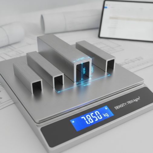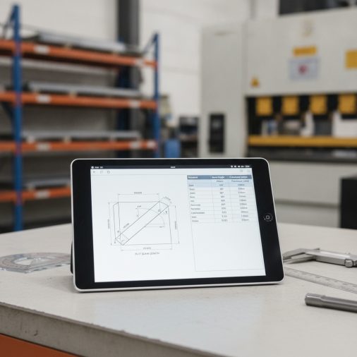
Getting the flat blank size right before you cut sheet metal is the difference between a part that fits perfectly and one that ends up in the scrap bin. This sheet metal development calculator computes the precise flat blank length, bend allowance, bend deduction, and outside setback for any combination of material thickness, bend angle, inside radius, and K-factor — so you can lay out your blanks with confidence whether you are working with mild steel, stainless, or aluminium on a press brake or hand brake.
Sheet Metal Development Calculator: Flat Blank Length & Bend Allowance
Calculate accurate flat blank lengths, bend allowances, and K-factors for sheet metal parts before cutting or forming.
How to Use This Calculator

Follow these steps to get accurate flat blank dimensions:
- Select your unit system — choose millimetres or inches; all inputs and outputs will use that unit.
- Enter material thickness — measure the actual gauge thickness with calipers, not the nominal gauge.
- Enter inside bend radius — this is the radius at the inside surface of the bend, typically stamped on your tooling.
- Enter bend angle — the angle through which the metal is bent (e.g., 90 for a right-angle bend).
- Enter or adjust the K-factor — use 0.33 for sharp bends in soft material, 0.41 for air-bending mild steel, and 0.50 for a neutral axis at mid-thickness.
- Enter Leg 1 and Leg 2 lengths — measure each flat leg from the outside mold line to the end of the part.
- Read the Bend Allowance, Bend Deduction, and Total Flat Blank Length from the results panel.
Understanding the Calculator Inputs
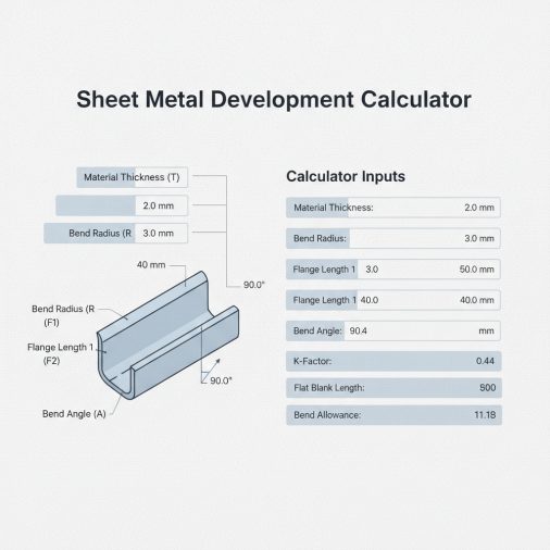
Unit System: Select Millimetres for metric work or Inches for imperial. All length inputs and outputs share the same unit — do not mix mm and inch values in the same calculation.
Material Thickness: Enter the actual measured thickness of your sheet, not the nominal gauge. A 16-gauge mild steel sheet is nominally 1.519 mm (0.0598 in), but real stock can vary. Using calipers gives you the most accurate blank development. If you are working with thin automotive panels, you may find useful context in this guide on welding automotive sheet metal precisely.
Inside Bend Radius: This is the radius measured at the inner surface of the bend — the side that contacts the punch tip or mandrel. It is usually marked on press-brake tooling. A smaller radius increases springback and work-hardening; a larger radius produces a softer, more gradual bend. For most air-bending operations, the inside radius is approximately 16% of the die opening width.
Bend Angle: Enter the angle through which the metal is bent, not the included angle of the finished part. A 90-degree bend means the metal turns 90 degrees from flat. A hem (180-degree fold) would be entered as 180, though the calculator caps at 179 to avoid a tangent singularity.
K-Factor: The K-factor describes where the neutral axis sits within the material cross-section during bending. A value of 0.25 represents a neutral axis very close to the inside surface (sharp, tight bends in soft material). A value of 0.50 places it exactly at mid-thickness (theoretical maximum for very large radii). Common starting values: 0.33 for sharp bends, 0.41 for standard air-bending of mild steel, 0.45 for aluminium, and 0.50 for large-radius bends. Adjust based on empirical test bends for critical production work.
Leg 1 and Leg 2 Lengths: Measure each flat leg from the outside mold line (the theoretical intersection of the two flat faces extended) to the end of the part. This is the dimension you would mark on a drawing as the overall flange length including the bend zone. Do not measure from the tangent point of the bend.
Understanding Your Results
Bend Allowance (BA): The arc length of the neutral axis through the bend zone. This is the actual amount of material consumed by the bend. It is always a positive number and increases with larger radii, thicker material, and larger bend angles.
Outside Setback (OSSB): The distance from the outside mold line to the tangent point of the bend on the outside surface. It is used to locate bend lines on a flat blank when working from outside dimensions. For a 90-degree bend it equals the sum of inside radius and material thickness.
Bend Deduction (BD): The amount subtracted from the sum of the two leg lengths to obtain the flat blank length. It equals two times the outside setback minus the bend allowance. A larger bend deduction means more material is effectively consumed by the geometry of the bend.
Total Flat Blank Length: The overall length of flat sheet required to produce the finished bent part. This is the primary output for nesting, ordering, and cutting. It equals Leg 1 + Leg 2 − Bend Deduction.
Neutral Axis Radius: The radius at which the neutral axis sits, calculated as inside radius plus K-factor times thickness. Material inside this radius is compressed; material outside is stretched.
Minimum Flange Length: A practical guideline equal to twice the sum of inside radius and thickness. Flanges shorter than this are difficult to form accurately on most press brakes because the die cannot grip the material properly.
Calculation Formulas Explained
All sheet metal development formulas are derived from the geometry of a circular arc. When a flat sheet is bent, the material on the inside of the bend compresses and the material on the outside stretches. Somewhere through the thickness there is a layer — the neutral axis — that neither stretches nor compresses. Its position is defined by the K-factor.
Neutral Axis Radius (R_n): R_n = inside_radius + k_factor * thickness. This is the radius of the arc that the neutral axis follows through the bend.
Bend Allowance (BA): BA = (pi * R_n * bend_angle) / 180. This is the arc length formula (angle in degrees converted to radians by dividing by 180 and multiplying by pi). It gives the length of material consumed in the curved zone.
Outside Setback (OSSB): OSSB = (inside_radius + thickness) * tan(bend_angle / 2). The outside setback is derived from the right-triangle geometry formed by the outside mold lines and the tangent point on the outside surface. The half-angle tangent gives the horizontal distance from the mold-line intersection to the tangent point.
Bend Deduction (BD): BD = 2 * OSSB - BA. This combines the two geometric setbacks and subtracts the actual arc length to give the net material reduction.
Total Flat Blank Length: Flat = Leg1 + Leg2 - BD. Subtracting the bend deduction from the sum of the outside-mold-line leg lengths gives the correct flat blank dimension.
All angle inputs are in degrees. The calculator converts them to radians internally using the factor pi/180 (3.14159265/180) before applying trigonometric functions.
Worked Example
Scenario: You need to bend a 2 mm thick mild steel bracket with a 90-degree bend, an inside radius of 2 mm, Leg 1 = 60 mm, Leg 2 = 40 mm, and a K-factor of 0.41.
- Neutral Axis Radius: R_n = 2 + 0.41 × 2 = 2 + 0.82 = 2.82 mm
- Bend Allowance: BA = (3.14159265 × 2.82 × 90) / 180 = (796.97) / 180 = 4.427 mm
- Outside Setback: OSSB = (2 + 2) × tan(45°) = 4 × 1.0 = 4.000 mm
- Bend Deduction: BD = 2 × 4.000 − 4.427 = 8.000 − 4.427 = 3.573 mm
- Total Flat Blank Length: Flat = 60 + 40 − 3.573 = 96.427 mm
- Minimum Flange Length check: 2 × (2 + 2) = 8 mm. Both legs (60 mm and 40 mm) exceed this, so the part is fully formable.
You would cut a blank of 96.43 mm, mark the bend line at 60 mm from one end (measured from the outside mold line), and form the 90-degree bend. The finished part will have outside leg dimensions of 60 mm and 40 mm as designed.
How to Interpret the Results
A larger bend allowance relative to the bend deduction indicates a large-radius, gradual bend — the neutral axis arc is long and the geometric setback is relatively small. A larger bend deduction relative to the bend allowance indicates a tight, sharp bend where the outside setback dominates.
If your Total Flat Blank Length comes out longer than expected, check that you are measuring legs from the outside mold line, not from the tangent point. Measuring from the tangent point is a common source of over-length blanks.
If test bends consistently produce parts that are slightly too long or too short, adjust the K-factor up or down by 0.01–0.02 increments and re-run the calculation. Empirical K-factor tuning is standard practice in production sheet metal work.
The Minimum Flange Length result is a planning guide. If either leg is shorter than this value, consider using a smaller punch radius, a narrower die, or a back-gauge stop to support the short flange during forming.
Common Mistakes to Avoid
- Measuring legs from the wrong reference: Always measure from the outside mold line (the intersection of the two extended flat faces), not from the start of the visible curve. Measuring from the tangent point adds the outside setback twice and produces an over-long blank.
- Using nominal gauge instead of measured thickness: Gauge tolerances can be ±5–10% on standard sheet. Always measure with calipers for critical parts.
- Applying a single K-factor to all materials: Aluminium, stainless steel, and mild steel have different work-hardening characteristics and require different K-factors. Using 0.41 for aluminium will produce slightly short blanks.
- Ignoring springback in the bend angle: This calculator computes flat development for the intended bend angle. If your press brake requires overbending to achieve the final angle due to springback, enter the final desired angle, not the overbend angle.
- Stacking errors across multiple bends: For parts with more than one bend, run a separate calculation for each bend and sum the flat lengths. Do not attempt to average K-factors across different bend radii in a single calculation.
- Confusing bend angle with included angle: A 90-degree bend produces an included angle of 90 degrees between the two legs. Some drawing conventions show the supplement (180 − 90 = 90 in this case, but for a 30-degree bend the included angle is 150 degrees). Always enter the angle the metal actually bends through.
Limitations and Important Notes
This calculator assumes a simple, single-radius air bend or bottom bend with uniform material properties throughout the bend zone. It does not account for: coining (where the punch tip penetrates the material and changes the K-factor significantly); rotary bending; roll forming; or multi-radius bends.
The K-factor is treated as a constant across the bend. In reality it varies slightly with bend radius-to-thickness ratio (r/t). For r/t ratios below 1, the K-factor drops toward 0.25–0.33; for r/t above 5, it approaches 0.50. The slider range of 0.25–0.50 covers the practical range for most press-brake work.
The minimum flange length result is a general guideline based on tooling geometry and does not account for specific press-brake die widths, back-gauge limitations, or material springback. Always verify against your actual tooling specifications.
Results are planning calculations only. Always produce a test bend on scrap material of the same batch, thickness, and temper before cutting production blanks. Material properties, tooling wear, and machine calibration all affect real-world results. This calculator does not constitute engineering certification or fabrication instruction for safety-critical components.
Frequently Asked Questions
What is the K-factor in sheet metal bending and how do I choose it?
The K-factor is a dimensionless ratio that describes where the neutral axis sits within the material thickness during bending. A value of 0.50 means the neutral axis is exactly at mid-thickness; lower values mean it has shifted toward the inside (compressed) surface due to work hardening and material flow. For standard air-bending of mild steel, 0.41 is the most widely used starting value. For soft aluminium, 0.45 is common. For very sharp bends (inside radius less than the material thickness), use 0.33 or lower. The most accurate approach is to bend a test piece, measure the actual flat blank consumed, back-calculate the K-factor, and use that value for production runs.
What is the difference between bend allowance and bend deduction?
Bend allowance (BA) is the actual arc length of material along the neutral axis through the bend zone — it is the physical length of sheet consumed by the curve. Bend deduction (BD) is a derived value used for practical layout: it is the amount you subtract from the sum of the two outside-mold-line leg lengths to get the correct flat blank length. BD equals two times the outside setback minus the bend allowance. Both values describe the same bend geometry from different reference perspectives; bend allowance is more fundamental, while bend deduction is more convenient for direct blank layout from outside dimensions.
How do I find the inside bend radius for my press brake tooling?
The inside bend radius in air bending is not simply the punch tip radius — it is determined primarily by the die opening width. A widely used rule of thumb is that the inside radius is approximately 16% of the V-die opening. For example, a 25 mm die opening produces roughly a 4 mm inside radius in 2 mm mild steel. The punch tip radius sets a minimum: the actual inside radius will never be smaller than the punch tip. For bottom bending and coining, the inside radius more closely matches the punch tip radius. Always measure a test bend with a radius gauge to confirm the actual inside radius before committing to production blank sizes.
Can I use this calculator for aluminium sheet metal?
Yes. Enter the actual measured thickness, the inside radius from your tooling, and adjust the K-factor to approximately 0.45 for 5052-H32 or 6061-T6 aluminium in standard air bending. Aluminium work-hardens differently from mild steel and tends to have a slightly higher K-factor for the same bend geometry. Aluminium also has more springback than mild steel, so your press brake may need to overbend to achieve the target angle — but enter the final desired angle in this calculator, not the overbend angle. Test bends are especially important with aluminium because batch-to-batch temper variation can shift the K-factor noticeably.
Why does my finished part come out slightly longer or shorter than calculated?
The most common causes are: using the wrong K-factor for your specific material and tooling combination; measuring leg lengths from the tangent point rather than the outside mold line; using nominal rather than measured material thickness; and springback changing the effective bend angle. Start by checking your measurement reference points, then verify thickness with calipers. If the error is consistent (always long or always short by a fixed amount), adjust the K-factor by 0.01–0.02 in the appropriate direction and re-run the calculation. Consistent small errors are almost always a K-factor calibration issue rather than a formula error.
How do I calculate a flat blank for a part with multiple bends?
For a part with multiple bends, calculate each bend individually using this calculator, then sum the results. Identify every flat leg length (measured from outside mold line to outside mold line for interior legs, or to the part end for terminal legs), calculate the bend deduction for each bend, and subtract each bend deduction from the total sum of all leg lengths. The flat blank length equals the sum of all leg lengths minus the sum of all bend deductions. Keep each bend’s K-factor, radius, and angle separate — do not average them. For complex multi-bend parts, a step-by-step spreadsheet approach using this calculator for each bend is the most reliable method.
What is the outside setback and when do I need it?
The outside setback (OSSB) is the distance from the outside mold line — the theoretical sharp corner where the two flat faces would meet if extended — to the tangent point where the bend curve begins on the outside surface. You need it when laying out bend lines on a flat blank using outside dimensions, or when calculating the position of a back gauge from the outside face of the part. For a 90-degree bend, the outside setback equals the sum of inside radius and material thickness, which is why many fabricators use that simple rule for right-angle bends. For other angles, the full tangent formula is required.
Does material grain direction affect the flat blank calculation?
Grain direction does not change the flat blank length calculation directly, but it significantly affects the K-factor and the risk of cracking. Bending perpendicular to the rolling direction (across the grain) produces a slightly higher K-factor and is generally safer for tight-radius bends. Bending parallel to the rolling direction (with the grain) increases the risk of cracking on the outside surface of the bend, particularly in harder alloys and tempers. For critical parts, orient the bend line perpendicular to the rolling direction where possible, and use a slightly more conservative (lower) K-factor when bending with the grain to account for the reduced ductility on the tension side of the bend.