
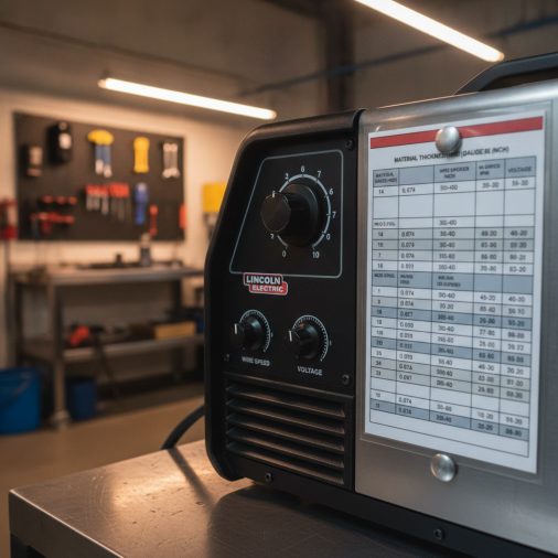
You just set up your Lincoln welder, but the settings inside the door don’t quite match your material, and you’re not sure which numbers to trust or how to adjust from there.
A Lincoln setting chart gives you a starting point for voltage, wire feed speed, or amperage based on your material thickness, process, and wire or electrode type. Because Lincoln Electric produces MIG, stick, TIG, and flux core machines across a wide range of models, the exact chart and recommended values will vary. Always cross-reference the chart on your specific machine with the wire or electrode manufacturer’s data.
What a Lincoln Setting Chart Actually Shows You
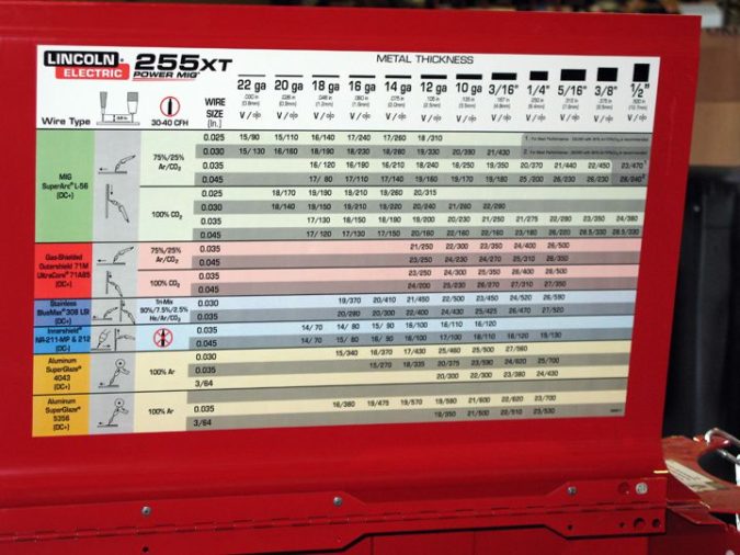
Lincoln Electric includes a reference chart on most of their welders — typically printed on a label inside the wire compartment door or in the operator’s manual. These charts list recommended settings organized by:
- Material thickness (usually in fractions of an inch or millimeters)
- Wire diameter for MIG and flux core machines
- Voltage range and wire feed speed (WFS)
- Electrode diameter and amperage range for stick machines
The chart is a starting point, not a final setting. Real-world variables like joint type, welding position, base metal condition, and shielding gas will require you to fine-tune from there.
Lincoln MIG Welder Settings Chart
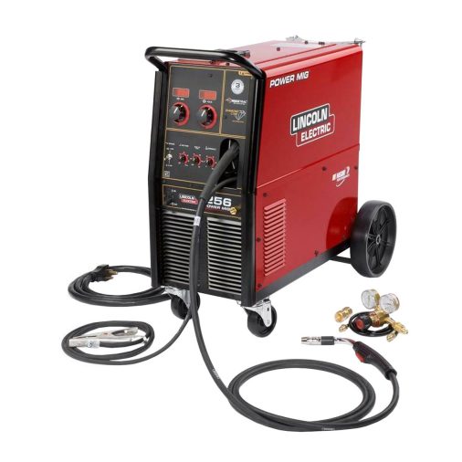
Wire, Voltage, and Wire Feed Speed
For Lincoln MIG welders running solid wire with a C25 shielding gas (75% argon / 25% CO₂), the chart typically maps settings across common mild steel thicknesses. The following table reflects the general structure of those charts. Treat these as starting ranges rather than exact specifications — your machine’s door chart and wire manufacturer’s data take priority.
| Material Thickness | Wire Diameter | Voltage (Approx.) | Wire Feed Speed (Approx.) |
|---|---|---|---|
| 24 gauge (0.6 mm) | 0.023 in | 13–15 V | 100–150 ipm |
| 18 gauge (1.2 mm) | 0.023–0.030 in | 14–16 V | 150–200 ipm |
| 1/8 in (3.2 mm) | 0.030–0.035 in | 17–19 V | 200–280 ipm |
| 3/16 in (4.8 mm) | 0.035 in | 18–20 V | 250–320 ipm |
| 1/4 in (6.4 mm) | 0.035 in | 19–22 V | 280–380 ipm |
For more detailed MIG wire reference data, the Lincoln MIG welder settings chart guide covers common Lincoln machines and how to read their door labels.
Polarity for MIG Welding
Standard solid wire MIG welding runs on DC electrode positive (DCEP). Confirm your machine’s polarity before striking an arc. Incorrect polarity causes poor penetration, excessive spatter, and an unstable arc.
Lincoln Flux Core Settings Chart
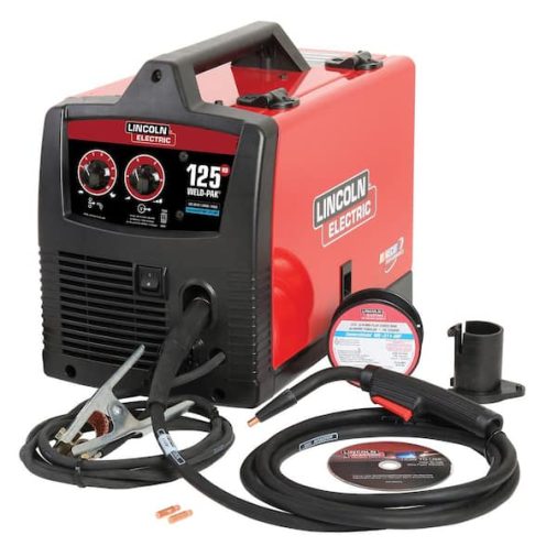
Self-Shielded vs. Gas-Shielded Flux Core
Lincoln Electric is well known for self-shielded flux core wires like the Innershield line. Self-shielded flux core runs on DC electrode negative (DCEN), which is the opposite polarity of solid wire MIG. Many Lincoln machines require you to swap the polarity leads inside the wire compartment when switching between processes.
Gas-shielded flux core (FCAW-G) runs DCEP and uses a separate shielding gas, similar in setup to standard MIG.
Typical Flux Core Starting Ranges
| Material Thickness | Wire Diameter | Voltage (Approx.) | Wire Feed Speed (Approx.) | Polarity |
|---|---|---|---|---|
| 16 gauge (1.5 mm) | 0.030 in | 14–16 V | 150–200 ipm | DCEN |
| 1/8 in (3.2 mm) | 0.035 in | 16–18 V | 200–260 ipm | DCEN |
| 3/16 in (4.8 mm) | 0.035 in | 17–20 V | 240–300 ipm | DCEN |
| 1/4 in (6.4 mm) | 0.045 in | 19–22 V | 260–340 ipm | DCEN |
Always verify polarity, as running self-shielded flux core wire on DCEP will produce a poor-quality weld. For a broader reference on flux core settings, the flux core MIG welding settings chart explains how to read and adjust these values for different wire types.
Lincoln Stick Welder Settings Chart
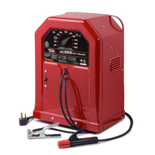
Lincoln stick welders such as the AC-225, Flextec series, and Invertec models cover a wide amperage range. The correct amperage depends on your electrode diameter, electrode classification, and base metal thickness.
| Electrode | Diameter | Typical Amperage Range | Polarity |
|---|---|---|---|
| E6010 | 1/8 in | 75–125 A | DCEP |
| E6011 | 1/8 in | 80–120 A | AC or DCEP |
| E6013 | 1/8 in | 80–130 A | AC, DCEP, or DCEN |
| E7018 | 1/8 in | 100–150 A | DCEP or AC |
| E7018 | 5/32 in | 130–200 A | DCEP or AC |
These ranges come from common electrode manufacturer data and serve as a starting reference. Joint position, fit-up, and base metal type all shift where you land within that range. A comprehensive breakdown of electrode-specific settings is available in this welding rod amperage chart.
Lincoln TIG Welder Settings
Lincoln TIG machines like the Square Wave TIG 200 use a rule of thumb of roughly 1 amp per 0.001 inch of material thickness for mild steel and stainless steel. Aluminum typically requires more amperage and runs on AC, while steel runs on DC electrode negative (DCEN).
For thin stainless or aluminum, the amperage drops quickly, and foot pedal control becomes essential. The TIG welding amps to metal thickness chart explains how to match amperage to material across common TIG applications.
How to Read the Door Chart on Your Lincoln Machine
Most Lincoln wire-feed machines have a sticker on the inside of the drive roll access door. Here is how to use it:
- Find your material thickness in the leftmost column.
- Read across to find the recommended wire diameter.
- Note the voltage setting — this may be listed as a dial position (A, B, C) or a numeric voltage range.
- Note the wire feed speed in inches per minute (ipm).
- Set the machine and run a test bead on scrap material before welding your actual workpiece.
If your machine’s voltage is set in switch positions rather than exact volts, the switch labels correspond to voltage ranges. Refer to your operator’s manual to find the voltage each position delivers.
Variables That Shift Your Starting Settings
No chart accounts for every real-world condition. These variables commonly require you to adjust from the chart’s baseline:
- Joint type: Fillet joints and groove joints absorb heat differently.
- Welding position: Overhead and vertical-up positions usually need slightly lower heat to control the puddle.
- Material condition: Mill scale, rust, paint, and galvanizing all affect arc stability and require clean prep or setting adjustments.
- Wire or electrode type: Changing from E71T-GS to E71T-11 or switching wire brands may shift the optimal setting.
- Work lead placement: Poor ground connection causes voltage drop and an unstable arc.
- Ambient temperature: Cold metal absorbs heat faster, sometimes requiring a slight increase in heat input.
Common Weld Problems and What to Adjust
| Symptom | Likely Cause | Adjustment |
|---|---|---|
| Stubbing wire into puddle | Voltage too low or WFS too high | Increase voltage or reduce WFS |
| Burn-through on thin material | Amperage or voltage too high | Reduce heat, use smaller wire, increase travel speed |
| Poor fusion, bead sitting on surface | Voltage too low | Increase voltage or reduce travel speed |
| Excessive spatter | Voltage too low or wrong polarity | Adjust voltage, check polarity |
| Rod sticking (stick welding) | Amperage too low | Increase amperage in small steps |
| Undercut on edges | Amperage too high or slow travel speed | Reduce amperage or speed up slightly |
Spatter issues in flux core welding are often related to polarity being set incorrectly, especially when switching from solid wire to self-shielded wire. Always check the wire manufacturer’s polarity requirement before welding.
Safety When Setting and Running a Lincoln Welder
Keep these points in mind before you strike an arc:
- Wear a properly rated welding helmet — at minimum shade 10 for MIG and flux core, shade 12 for higher-amperage stick or TIG.
- Use flame-resistant clothing, welding gloves, and closed-toe leather footwear.
- Ensure adequate ventilation, especially when running self-shielded flux core, which produces more fume than solid wire MIG.
- Secure shielding gas cylinders upright and chained to a fixed support.
- Keep flammable materials away from the arc and spatter zone.
- Inspect cables and connections for damage before every session. Damaged insulation is a shock and fire risk.
For structural, pressure-bearing, or code-governed work, starting from a door chart is not sufficient. A qualified welding procedure specification and appropriate testing are required.
Frequently Asked Questions
Where is the settings chart on a Lincoln MIG welder?
Most Lincoln MIG and flux core machines have the settings chart printed on a label inside the wire compartment door. If the label is missing or unreadable, download the operator’s manual from Lincoln Electric’s website using your machine’s model number. The manual includes the full recommended settings table.
How do I know if my Lincoln welder settings are correct?
Run a test bead on scrap material of the same thickness and type as your workpiece. A correct setting produces a smooth, consistent arc sound, minimal spatter, good fusion at the toes of the weld, and a bead with even width and height. Cut and etch the bead to check penetration when the application demands it.
Can I use the same Lincoln settings chart for flux core and solid MIG wire?
No. Flux core and solid wire use different voltages, wire feed speeds, and polarity. Self-shielded flux core runs DCEN, while solid MIG wire runs DCEP. Many Lincoln machines print separate columns or separate charts for each wire type. Always confirm which wire type the chart section applies to.
What does the Lincoln welder voltage dial or switch position mean?
On machines with stepped voltage switches, each switch position corresponds to a voltage range rather than a single exact value. Your operator’s manual lists what voltage output each position delivers. On continuously adjustable machines, the voltage display or scale shows the actual set voltage.
Does material thickness alone determine Lincoln welder settings?
Thickness is the primary factor, but not the only one. Wire diameter, electrode type, joint design, welding position, shielding gas, and base metal condition all affect the ideal setting. The door chart gives you a starting point based on thickness, and you adjust from there based on how the arc and puddle behave.
Why does my bead look different from the same settings I used last time?
Common causes include a different base metal condition (rust, scale, or coating), a worn or partially blocked contact tip, a loose work lead connection, low shielding gas flow, or a worn drive roll. Check consumables and connections before assuming the settings need to change.
Using the Chart as a Foundation, Not a Final Answer
A Lincoln setting chart gets you close, but the final setting comes from observing how the arc and puddle behave on your actual material. Use the door chart or operator’s manual as your starting reference, verify polarity for your wire type, and always run a test bead on scrap before committing to the actual joint.
For critical or regulated work, a door chart is only the beginning. A qualified welding procedure, proper joint preparation, and inspection are necessary to confirm the weld meets the application’s requirements. Consistent weld quality comes from understanding what each variable does — not just memorizing a number.


