
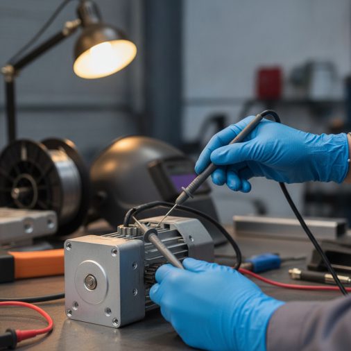
A failing drive motor is one of the most frustrating MIG welder problems to diagnose because its symptoms overlap with so many other issues — wire feed stuttering, burn-back, inconsistent arc. Before you replace an expensive component or tear apart your wire feed assembly, you need to confirm the motor itself is actually the problem. This guide walks you through every practical step to test a MIG drive motor correctly, using tools you likely already own.
Quick Answer
To test a MIG drive motor, use a multimeter to check voltage at the motor terminals while the trigger is active. A healthy motor typically receives 24–90V DC depending on the machine. Also check motor resistance (usually 5–50 ohms at the brushes) and physically inspect for brush wear, armature damage, and binding in the shaft.
What the Drive Motor Actually Does
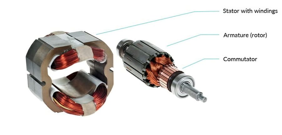
The drive motor is the small DC motor inside your wire feeder that pushes electrode wire from the spool through the liner and out the contact tip. It runs whenever you pull the trigger, and its speed directly controls wire feed rate.
When it fails — or starts failing — the arc becomes unstable. You might see wire stubbing into the puddle, burn-back at the tip, or wire that feeds in surges rather than smoothly.
The tricky part is that a worn liner, a kinked wire path, or a slipping drive roll can produce identical symptoms. Testing the motor in isolation eliminates it as a cause before you start replacing other parts.
Tools You Need Before You Start
You don’t need specialized equipment. The following covers everything:
– Digital multimeter (with DC voltage and resistance/ohms function)
– Screwdrivers (Phillips and flathead)
– Wire brush or fine emery cloth
– Needle-nose pliers
– Marker or tape for labeling wires
– Safety glasses
Optional but useful:
– Clamp-style ammeter to measure motor current draw under load
– Bench power supply (for isolated motor bench testing)
Safety First — Do This Before Touching Anything

MIG welders carry lethal voltages internally. Even with the machine powered off, capacitors in the power supply can hold a charge.
– Disconnect the machine from the wall outlet completely
– Wait at least 60 seconds before opening any panels
– Never probe inside the main power supply section with a multimeter unless you are a qualified electrician
– Keep the work area dry
The drive motor circuit itself typically operates at low DC voltage (12–90V depending on the machine), but the surrounding components do not.
Step-by-Step: How To Test a MIG Drive Motor

Step 1 — Visual Inspection First
Before any electrical testing, open the wire feed compartment and look at the motor directly.
Check for:
– Burnt smell or discoloration around the motor body
– Carbon dust (black powder) around the brush holders — a sign of heavy brush wear
– Corrosion on terminals or connector pins
– Physical damage to the motor housing or shaft
Spin the motor shaft by hand. It should rotate freely with only slight magnetic resistance. If it’s stiff, grinds, or doesn’t spin at all, the motor has a mechanical fault — bearings or a seized armature.
Step 2 — Check the Motor Terminals for Voltage
This test confirms whether the motor is receiving power when it should be.
1. Reconnect the machine to power (do not open any panels)
2. Set your multimeter to DC Voltage, range above 90V
3. Locate the two motor terminals — usually accessible at the motor connector without disassembly
4. Place probes on the positive and negative terminals
5. Pull the welding trigger briefly while watching the meter
What you’re looking for:
| Reading | Interpretation |
|---|---|
| Correct voltage (per machine spec) | Power is reaching the motor — fault may be in the motor itself |
| Zero volts | No power reaching motor — check trigger circuit, PCB, or wiring |
| Fluctuating/unstable voltage | Control board or trigger switch issue |
| Voltage present but motor doesn’t run | Motor is faulty |
Most machines list the motor voltage on the wiring diagram inside the panel cover. Common values are 24V, 42V, or 90V DC.
Step 3 — Measure Motor Winding Resistance
With the machine fully disconnected from power, disconnect the motor from its wiring harness.
Set your multimeter to the ohms (Ω) function.
– Place probes directly on the motor’s two power terminals
– Record the resistance reading
Typical resistance values:
| Motor Condition | Resistance Reading |
|---|---|
| Healthy motor | 5–50 ohms (varies by motor size) |
| Open winding (broken internally) | OL / infinite (no continuity) |
| Shorted winding | Near 0 ohms |
An open reading means the armature winding or brush circuit is broken — the motor won’t run. A near-zero reading suggests a shorted winding, which typically causes the motor to run hot and draw excessive current.
Step 4 — Inspect and Test the Carbon Brushes
Most MIG drive motors use carbon brushes to transfer current to the rotating armature. These wear down over time and are one of the most common causes of motor failure.
To access the brushes:
1. Remove the motor from the feeder assembly (usually 2–4 screws)
2. Locate the brush holders on the motor body — typically two small caps or clips on opposite sides
3. Remove the brushes carefully
What to check:
– Length: Brushes shorter than 5–6mm (or less than half their original length) should be replaced
– Surface: The contact face should be smooth and slightly curved. A flat, chipped, or cracked face causes poor contact
– Spring tension: The spring behind each brush should push it firmly against the armature. A weak or broken spring causes intermittent contact
– Armature surface: Look through the brush hole at the copper commutator. It should be smooth and copper-colored. Black glazing, deep grooves, or pitting indicates wear
Clean light carbon buildup from the commutator with fine emery cloth. Do not use sandpaper — it leaves abrasive particles that accelerate wear.
Step 5 — Bench Test the Motor Directly
If voltage is reaching the motor but it still won’t run, isolate it completely and test it on its own.
Using a bench power supply or a known good 12V DC source (such as a car battery with appropriate current limiting):
1. Connect positive to one motor terminal, negative to the other
2. Apply power briefly
The motor should spin smoothly and consistently. Listen for grinding, squealing, or intermittent stopping — all signs of internal damage.
Reverse the polarity. The motor should spin in the opposite direction. If it only runs in one direction or not at all on direct power, the motor is confirmed faulty.
Step 6 — Check Current Draw Under Load
A motor that runs but feels weak may be drawing too much or too little current. This requires a clamp ammeter around one of the motor supply wires while the feeder is running.
Compare the reading to the motor’s rated current (found on the motor label or machine documentation).
– Higher than rated current: Motor is straining — possible mechanical binding, worn bearings, or a shorted winding
– Lower than rated current: Possible brush wear or poor electrical contact
– Normal current but poor feed: The problem is mechanical — drive rolls, liner, or contact tip
Common Symptoms and What They Actually Mean
| Symptom | Most Likely Cause |
|---|---|
| Wire feeds in bursts, not smoothly | Worn brushes or intermittent brush contact |
| Motor hums but shaft doesn’t turn | Seized bearings or stalled armature |
| Motor runs but wire doesn’t feed | Drive roll slip or stripped gear |
| Motor runs only when trigger is held hard | Faulty trigger switch, not the motor |
| Burning smell from feeder area | Shorted motor winding or overloaded motor |
| Inconsistent wire speed at same setting | Control board issue or worn potentiometer |
What To Check Before Replacing the Motor
Field experience shows that motors get replaced unnecessarily because the actual fault is elsewhere. Before ordering a new motor, confirm:
– Drive rolls are the correct size and properly tensioned — too tight causes motor overload
– The wire liner is clean and not kinked — a blocked liner dramatically increases motor load
– The contact tip is not partially blocked — wire resistance at the tip can stall the motor
– The control board is supplying stable voltage — a failing PCB mimics a dead motor perfectly
A motor that tests fine electrically but still underperforms is almost always fighting a mechanical restriction somewhere in the wire path.
FAQ
How do I know if my MIG wire feed motor is bad?
The clearest signs are wire feeding inconsistently despite correct drive roll tension, the motor humming without the shaft turning, or zero voltage at the motor terminals when the trigger is pulled. Confirm with a multimeter resistance test — an open or shorted winding reading is definitive proof the motor has failed internally.
Can I test a MIG drive motor without a multimeter?
You can do a basic visual inspection and a direct-power bench test using a 12V DC source, but you can’t accurately diagnose winding faults or confirm voltage delivery without a multimeter. A basic digital multimeter costs under $20 and is worth having for any welding equipment maintenance.
What voltage does a MIG drive motor run on?
Most MIG drive motors operate on DC voltage between 24V and 90V, depending on the machine’s design and wire feed speed range. The exact value is usually printed on the motor label or listed in the machine’s wiring diagram. Always verify before testing to know what a correct reading looks like.
How long do MIG drive motor brushes last?
Carbon brushes typically last between 500 and 1,500 hours of actual motor run time, though this varies significantly based on motor load, wire type, and how often the feeder starts and stops. Machines used for short tack welds cycle the motor more frequently, which accelerates brush wear faster than continuous production welding.
Why does my MIG wire feed motor run but the wire won’t feed?
If the motor shaft spins freely but wire doesn’t move, the problem is mechanical rather than electrical. Check whether the drive roll is slipping on the shaft, the set screw is loose, or the drive roll groove doesn’t match the wire diameter. An internal gear strip in the feeder gearbox can also cause this.
Can a bad MIG drive motor damage the welder’s control board?
Yes. A shorted motor winding draws excessive current, which can overheat the motor control circuit on the PCB. If you suspect a shorted motor (near-zero resistance reading), replace it before powering the machine on again. Running a shorted motor even briefly can destroy an expensive control board.
Is it worth repairing a MIG drive motor or just replacing it?
Brush replacement is almost always worth doing — brushes are inexpensive and the repair is straightforward. If the armature windings are shorted or open, replacement is typically more practical than rewinding. Replacement motors for common machines like the Lincoln Electric SP-series or Miller Millermatic range from $40 to $150, which is usually less than a repair shop labor charge.
Final Thoughts
Testing a MIG drive motor is a logical process — start with visual inspection, confirm voltage delivery, measure winding resistance, and check the brushes before assuming the motor is dead. Most apparent motor failures turn out to be worn brushes, a blocked liner, or a control board issue. When the motor does test faulty, replacing it is straightforward and far less expensive than guessing wrong and replacing components that were never the problem.
Meta Description:
Struggling with inconsistent wire feed? Learn how to test a MIG drive motor step by step using a multimeter — diagnose faults fast before replacing parts.


