Picking the wrong wire diameter is one of the most common reasons a MIG weld underperforms. The wire feeds too slowly, the arc sputters, or the base metal burns through before you’ve laid half a bead.
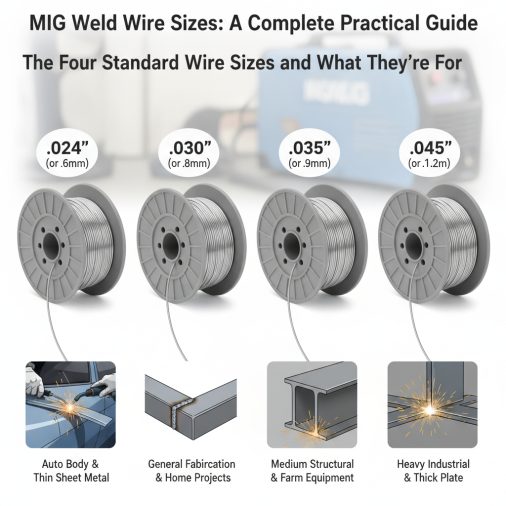
MIG welding wire comes in four standard diameters: 0.023″, 0.030″, 0.035″, and 0.045″. Thinner wire (0.023″–0.030″) suits thin sheet metal and low-amperage machines, while 0.035″ is the most versatile all-around choice for home shops and general fabrication. Heavy structural work typically calls for 0.045″. Match wire size to material thickness and your welder’s amperage range.
The Four Standard Wire Sizes and What They’re For
Most hobbyist and professional welders work with one of four diameters. Each has a specific range of applications based on material thickness, amperage, and machine capability.
Wire Diameter
Best For
Typical Amperage Range
0.023"
24–18 gauge sheet metal
30–100A
0.030"
18 gauge–3/16" mild steel
40–145A
0.035"
14 gauge–1/2" mild steel
50–200A
0.045"
3/16"–1" structural steel
150–350A
The 0.035″ diameter consistently shows up as the default choice for machines in the 140–200A class, which covers the majority of home shop and light industrial welders. It handles a wide enough range of thicknesses to be genuinely useful across most projects.
How Material Thickness Drives Wire Selection
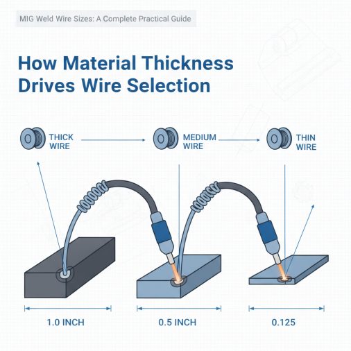
The fundamental rule is straightforward: thinner metal needs thinner wire. Thicker wire carries more current and deposits more filler metal per unit of time. On thin material, that excess heat and deposition rate causes burn-through almost instantly.
For sheet metal work—automotive body panels, HVAC ductwork, or anything under 1/8″—0.023″ or 0.030″ wire gives you the control needed to lay tight, consistent beads. If you regularly work on MIG welding sheet metal, 0.023″ wire on a machine set to low amperage gives the most forgiving arc.
For medium-thickness steel from roughly 1/8″ to 5/16″, 0.035″ wire is the practical standard. It welds comfortably at mid-range settings without requiring the precision that thinner wire demands.
Anything 3/8″ and above benefits from 0.045″ wire, provided your machine has the amperage to drive it properly. Running 0.045″ wire on a 140A machine produces a cold, underpen bead with poor fusion.
How Welder Amperage Affects Wire Size Choice
Wire diameter and amperage are directly linked. Every wire size has a usable amperage range, and running outside that range degrades weld quality.
Running thin wire at high amperage causes the wire to burn back toward the contact tip, leading to tip contamination and erratic arcing. Running thick wire at low amperage produces cold welds with poor penetration and a high, ropy bead profile.
A practical check: if your welder’s maximum output is below 130A, 0.035″ wire is likely your upper limit. If you’re running a machine like the Lincoln Electric Weld-Pak 140 HD, 0.025″ or 0.030″ wire is the manufacturer’s sweet spot for most of its usable range.
Most welder manufacturers publish a wire size recommendation in the manual or inside the door panel. That recommendation reflects the machine’s actual tested performance—it’s worth following.
Wire Sizes for Different Base Materials
Wire diameter selection also shifts depending on the base material, not just thickness.
Mild Steel
The standard sizes (0.023″–0.045″) all apply directly to mild steel. Most ER70S-6 solid wire comes in all four diameters, giving you full flexibility.
Stainless Steel
Stainless wire typically runs in 0.030″ and 0.035″ for most shop applications. The higher chromium and nickel content makes stainless wire slightly stiffer, so welding stainless with a MIG welder requires careful attention to liner condition and drive roll pressure.
Aluminum
Aluminum MIG wire is almost exclusively used at 0.030″ and 0.035″ for light fabrication, with 3/64″ (approximately 0.047″) used on heavier structural aluminum. Aluminum wire is softer and requires a spool gun or push-pull system to avoid bird-nesting in standard torch setups. Wire composition matters here too—ER4043 and ER5356 are the two dominant alloys, and understanding what MIG welding wire is made of helps when choosing between them.
Flux-Core Wire
Flux-core wire follows slightly different conventions. The most common sizes are 0.030″, 0.035″, and 0.045″. The 0.030″ flux-core is popular for gasless welding on thin to medium material, though it produces more spatter than solid wire at the same diameter. For more on when gas is and isn’t required, this breakdown on gas requirements for MIG welding covers both processes clearly.
Solid Wire vs. Flux-Core: Does Size Work the Same Way?
Not entirely. Flux-core wire deposits more filler metal per amp compared to solid wire of the same diameter. This happens because the flux core takes up space that would otherwise be metal, but the outer sheath still carries the arc current.
In practical terms, 0.030″ flux-core wire often behaves more like 0.035″ solid wire in terms of deposition rate. This means slightly lower voltage and wire speed settings are usually needed when switching from solid to flux-core at the same nominal diameter.
Flux-core also generally tolerates mill scale, rust, and contamination better than solid wire—which is why it’s commonly preferred for outdoor structural work and repair jobs where surface preparation is limited.
Wire Size and Travel Speed Relationship
Wider wire diameter doesn’t just mean more heat—it also affects travel speed. Larger diameter wire deposits more material per inch of weld, which means you need to move faster to maintain a consistent bead width and avoid piling up filler.
Beginners often discover this the hard way. Switching from 0.030″ to 0.035″ without adjusting travel speed produces a wide, convex bead that lacks penetration and looks overbuilt. Recognizing what a good MIG weld looks like helps you catch this quickly and adjust before it becomes a habit.
The fix is simple: increase travel speed slightly when stepping up wire diameter, and verify your settings on scrap before moving to the actual workpiece.
Common Wire Size Mistakes
Using 0.035″ wire on thin automotive sheet metal. This is the most frequent error in home shops. Even at minimum settings, 0.035″ wire on 20-gauge steel almost always causes burn-through or excessive distortion. Drop to 0.023″ or 0.030″.
Running 0.030″ wire on heavy plate and wondering why penetration is shallow. Thin wire at high amperage burns back erratically and doesn’t carry enough filler to fill a joint on thick material. Step up to 0.035″ or 0.045″ and adjust machine settings accordingly.
Mismatching drive rolls to wire size. Drive rolls are sized for specific wire diameters and have V-groove or U-groove profiles to match wire type. Running 0.035″ wire through a drive roll sized for 0.030″ causes inconsistent feeding, which can look identical to a wire feed motor problem until you check the roll spec.
Not adjusting gas coverage when changing wire size. Larger wire diameter at higher amperages benefits from slightly increased shielding gas flow rate—typically 25–30 CFH instead of the 20 CFH that works fine with 0.030″ wire. Porosity in the weld is often the first sign that gas coverage is insufficient.
Quick Wire Size Reference Chart
Material Thickness
Recommended Wire Size
Process
24–22 gauge
0.023"
Solid/Gas
20–18 gauge
0.023"–0.030"
Solid/Gas
16–14 gauge
0.030"–0.035"
Solid/Gas or Flux-Core
1/8"–3/16"
0.035"
Solid/Gas or Flux-Core
1/4"–3/8"
0.035"–0.045"
Solid/Gas or Flux-Core
1/2" and above
0.045"
Solid/Gas or Flux-Core
FAQ
What is the most common MIG wire size for home welders?
0.035″ is the most commonly used wire size in home and small shop environments. It handles the majority of mild steel projects from 14 gauge up to about 5/16″ thick, and most 140–200A hobby welders are set up to run it efficiently. It’s also the default wire size that ships with many mid-range machines.
Can I use 0.030 wire instead of 0.035 in my MIG welder?
Yes, in most cases. Your machine needs to have a drive roll that matches 0.030″ wire, and you’ll need to adjust the contact tip. Running thinner wire requires slightly higher wire feed speed to maintain the same arc characteristics. For thin material, the switch is often worth it—you gain better control and reduce the risk of burn-through.
What wire size should I use for automotive body panels?
0.023″ wire is the preferred choice for automotive body panels, which are typically 18–22 gauge steel. This diameter minimizes heat input, reducing warping and burn-through risk. Pair it with a short-circuit transfer process and pulse-style technique. Some experienced fabricators use 0.025″ as a middle ground when working on panels that vary between 16 and 20 gauge.
Does wire size affect MIG weld spatter?
Wire size itself isn’t the primary cause of spatter, but it contributes indirectly. Thicker wire at higher amperages tends to produce more spatter if voltage isn’t matched correctly. Flux-core wire produces more spatter than solid wire regardless of diameter. Matching wire diameter to your amperage range and tuning voltage carefully are the most effective ways to minimize spatter.
What wire size is best for welding exhaust pipes?
Exhaust pipe is typically thin-wall tubing in the 16–18 gauge range. 0.030″ solid wire with 75/25 argon-CO2 shielding gas is a reliable choice. Some welders prefer 0.023″ for especially thin-wall tubing. Proper wire selection is one of several factors covered when approaching exhaust pipe welding with a MIG setup.
What’s the difference between 0.035 and 0.045 MIG wire?
The 0.045″ wire has roughly 65% more cross-sectional area than 0.035″, which means significantly higher deposition rates at equivalent or higher amperages. It’s designed for heavier structural work on machines rated above 200A. Running 0.045″ wire on a light-duty machine produces poor fusion and a cold bead—this wire size needs real amperage behind it to perform correctly.
Can you use MIG wire sizes interchangeably without changing machine settings?
No. Changing wire diameter requires adjusting wire feed speed, voltage, and sometimes shielding gas flow. It also requires matching the drive roll groove size and contact tip to the new wire diameter. Skipping these adjustments causes feeding problems, arc instability, and poor weld quality. Always treat a wire size change as a full machine re-setup.
Wire diameter is one of the first decisions that shapes every other variable in a MIG weld. Get it right for the material and machine, and everything from arc stability to bead appearance improves. For most general fabrication, 0.035″ ER70S-6 is a dependable starting point—but always step down to 0.030″ or 0.023″ when sheet metal or thin-wall tubing is involved. The goal is matching the wire to the job, not defaulting to whatever’s already loaded.