
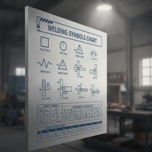
Welding symbols are the universal language of fabrication. Whether you’re a welder on the shop floor or an engineer reviewing blueprints, understanding these symbols is essential. This article breaks down everything you need to know about welding symbols charts — what they mean, how to read them, and how to apply them correctly on real projects.
A welding symbols chart is a reference guide that shows standardized symbols used on engineering drawings to communicate weld type, size, location, and finishing requirements. These symbols follow AWS A2.4 or ISO 2553 standards. Reading them correctly ensures welds are placed in the right location, with the right process and dimensions.
—
Why Welding Symbols Exist
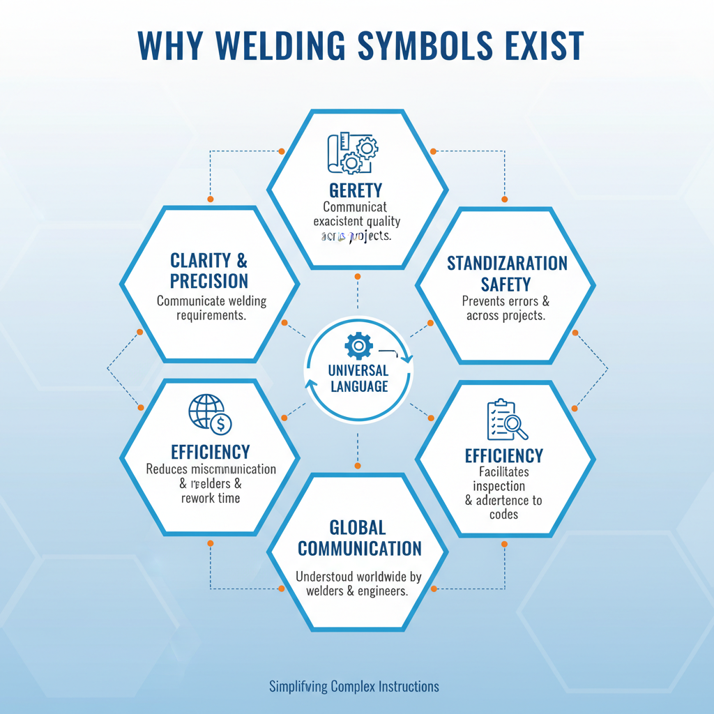
Before welding symbols were standardized, fabricators relied on written notes and verbal instructions. This caused errors, miscommunication, and inconsistent welds across job sites.
Welding symbols solve that problem. A single symbol on a drawing can communicate the weld type, joint location, groove angle, root opening, and finishing method — all without a single word.
The American Welding Society (AWS) publishes the A2.4 standard, which is the most widely used in North America. ISO 2553 is the international equivalent used across Europe and much of Asia.
—
The Anatomy of a Welding Symbol
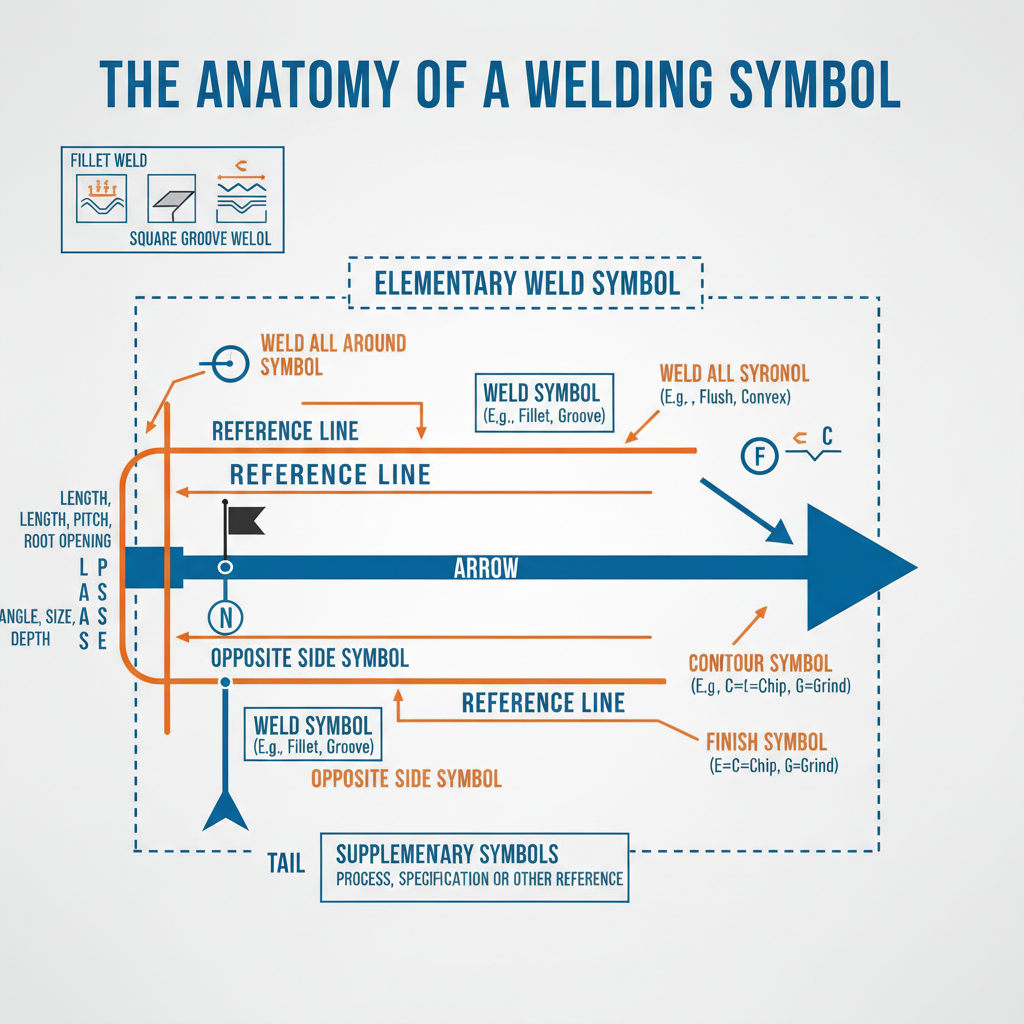
Every welding symbol is built around a reference line — a horizontal line that anchors all other information. Understanding each component of this structure is the foundation of reading any welding symbols chart.
Here are the key parts:
– Reference line — The horizontal baseline of the symbol
– Arrow — Points to the joint or weld location on the drawing
– Weld symbol — Placed on or above the reference line to indicate weld type
– Tail — Optional section at the end of the reference line; contains process or specification notes
– Dimensions — Numbers placed to the left (size/depth) and right (length/pitch) of the weld symbol
– Supplementary symbols — Add information about contour, backing, or weld-all-around requirements
The arrow side refers to the side of the joint the arrow physically points to. The other side is the opposite face of the joint. Symbols placed below the reference line apply to the arrow side. Symbols above the reference line apply to the other side.
—
Common Weld Types and Their Symbols
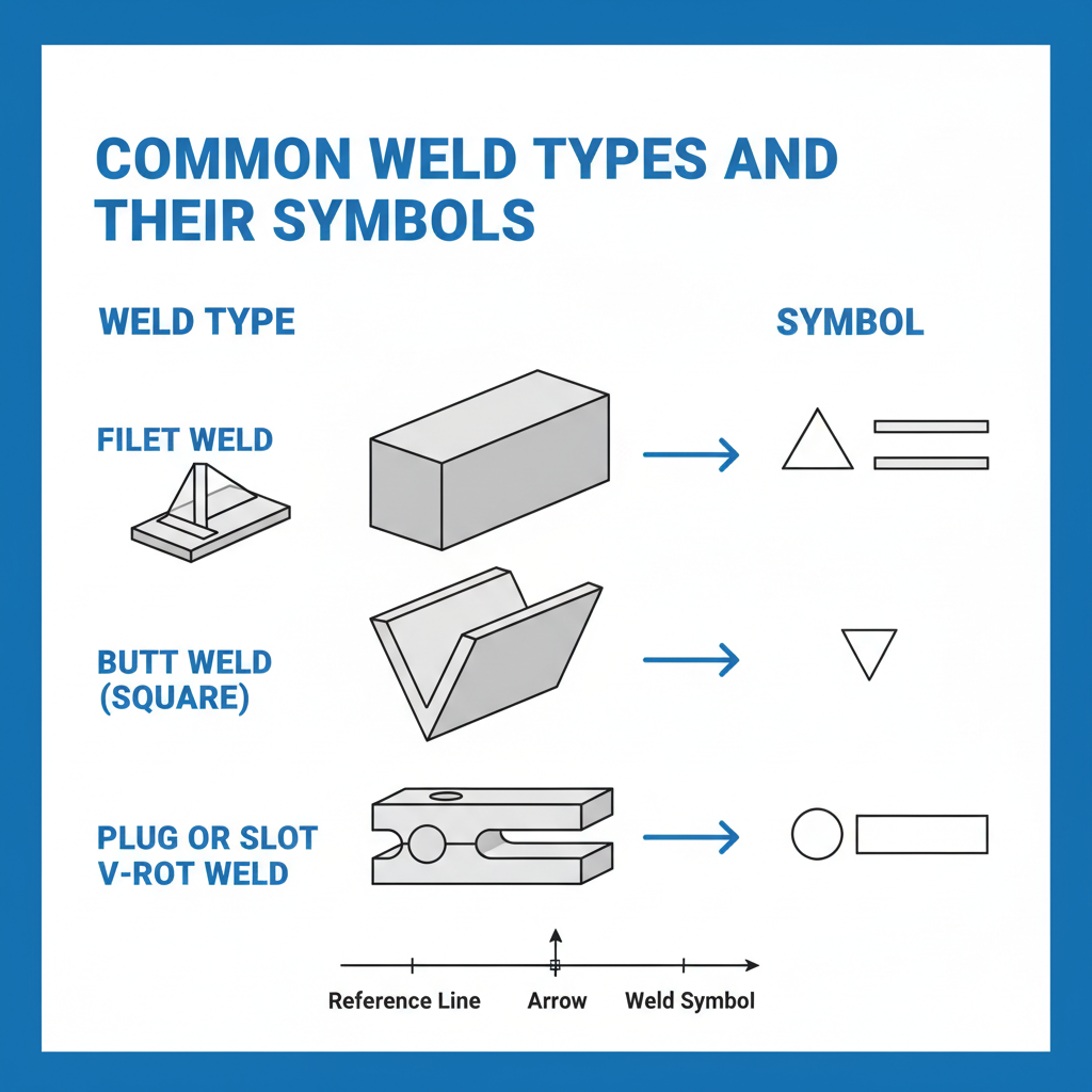
This is the core of any welding symbols chart. Each weld type has a distinct symbol shape.
| Weld Type | Symbol Shape | Common Use |
|---|---|---|
| Fillet weld | Right triangle | Lap joints, T-joints |
| Groove (V-groove) | V shape | Butt joints, full penetration |
| Square groove | Two parallel lines | Thin material butt joints |
| U-groove | U shape | Heavy plate, pressure vessels |
| J-groove | J shape | One-sided deep groove welds |
| Plug/slot weld | Circle or rectangle | Overlapping sheet metal |
| Spot weld | Circle with center dot | Sheet metal, resistance welding |
| Seam weld | Circle with two lines | Continuous sheet metal joints |
| Back/backing weld | Semicircle | Root reinforcement on groove welds |
| Surfacing weld | Flat line with wave | Hard-facing, build-up applications |
Fillet and V-groove welds are the most frequently encountered in structural and manufacturing work. Field experience shows that misreading a fillet symbol size causes more rework than almost any other drawing error.
—
How to Read Dimensions on a Welding Symbol
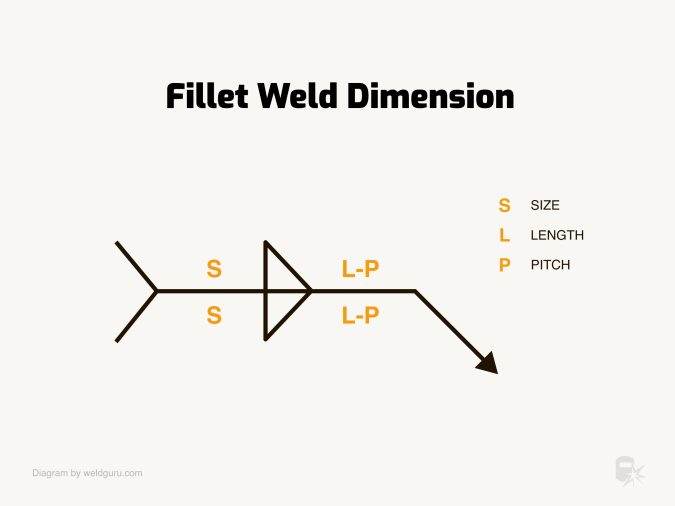
Dimensions tell the welder exactly how large and how long the weld should be. They appear as numbers flanking the weld symbol on the reference line.
For fillet welds:
– The number to the left of the symbol = leg size (e.g., 3/8″)
– The number to the right = weld length (e.g., 2″)
– A hyphen between two numbers on the right = intermittent weld (length-pitch format, such as 2-6, meaning 2″ weld every 6″ center-to-center)
For groove welds:
– The number in parentheses = depth of groove preparation
– The number outside parentheses = effective throat or weld size
– The angle shown = groove angle (e.g., 60°)
– Root opening appears at the bottom of the groove symbol
In practice, missing or misreading a root opening dimension on a groove weld can lead to incomplete fusion — a serious structural defect.
—
Supplementary Symbols You Need to Know
Supplementary symbols add finishing or location requirements on top of the basic weld symbol. These appear frequently in quality-critical applications.
– Weld-all-around — A circle at the arrow/reference line junction; means the weld continues around the entire joint
– Field weld — A filled flag at the junction; indicates the weld is made on-site, not in the shop
– Flush contour — A flat line above or below the weld symbol; the weld surface must be ground or finished flat
– Convex contour — A curved line; the weld face should remain convex
– Concave contour — An inward curve; used where smooth blending is required
– Melt-through — A filled circle; indicates full penetration from one side with visible reinforcement on the back
Contour symbols are often paired with finishing method letters: G for grinding, C for chipping, M for machining.
—
AWS vs. ISO Welding Symbol Differences
A common issue technicians encounter is receiving drawings that mix AWS and ISO conventions. The two systems are similar but have key differences that can cause errors.
| Feature | AWS A2.4 | ISO 2553 |
|---|---|---|
| Arrow side placement | Symbol below reference line | Symbol below reference line |
| Other side placement | Symbol above reference line | Symbol above reference line |
| Dashed line use | Not used | Dashed line = other side |
| Weld-all-around | Circle at junction | Circle at junction |
| Tail use | Process/specification notes | Process/specification notes |
| Fillet symbol orientation | Triangle points right | Triangle points right |
The most practical difference: ISO drawings sometimes use a dashed reference line to indicate the other side of the joint, while AWS does not. Always confirm which standard a drawing follows before fabricating.
—
Most Common Mistakes When Reading Welding Symbols
Even experienced welders misread symbols under pressure. These are the errors that show up most often in the field.
– Ignoring arrow side vs. other side — Placing a weld on the wrong face of the joint is a frequent and costly mistake
– Missing intermittent weld spacing — Reading only the length without the pitch leads to continuous welds where intermittent ones were specified
– Overlooking the tail — The tail often specifies the welding process (SMAW, GMAW, GTAW) or a specific procedure; skipping it can result in non-conforming welds
– Confusing groove depth with weld size — These are two different dimensions and must not be treated as interchangeable
– Ignoring finishing symbols — A flush contour requirement means post-weld grinding is mandatory, not optional
A quick habit that helps: before starting any weld, trace the full symbol from arrow to tail and confirm every dimension and supplementary symbol is accounted for.
—
FAQ
What is the most common welding symbol on structural drawings?
The fillet weld symbol is the most common. It appears on T-joints, lap joints, and corner joints throughout structural steel and manufacturing work.
What does a circle on a welding symbol mean?
A small circle at the junction of the arrow and reference line means “weld all around.” A circle with a center dot represents a spot weld.
How do I know if a weld goes on both sides of a joint?
If weld symbols appear both above and below the reference line, the weld is required on both sides of the joint.
What does the tail of a welding symbol contain?
The tail holds supplementary information such as the welding process (e.g., GTAW), a welding procedure specification (WPS) number, or special notes from the engineer.
What is the difference between weld size and throat on a fillet weld?
Weld size refers to the leg length of the fillet. The effective throat is the perpendicular distance from the root to the weld face — approximately 0.707 times the leg size for equal-leg fillets.
Can I use an AWS symbol chart for ISO drawings?
Not reliably. While many symbols look similar, the dashed line convention and some symbol placements differ. Always identify the standard used on the drawing title block.
Where can I find an official welding symbols chart?
The AWS A2.4 standard is the authoritative source in North America. Many welding supply companies and the Lincoln Electric welding library also publish free reference charts based on this standard.
—
Final Thoughts
Welding symbols are a precise communication tool. A single symbol encodes weld type, size, location, contour, and process — all in a compact notation that leaves no room for guesswork when read correctly.
The most important habits are confirming which standard the drawing uses, reading both sides of the reference line, and never skipping the tail. With a solid welding symbols chart as a reference and consistent practice reading drawings, interpreting even complex fabrication blueprints becomes straightforward and reliable.


