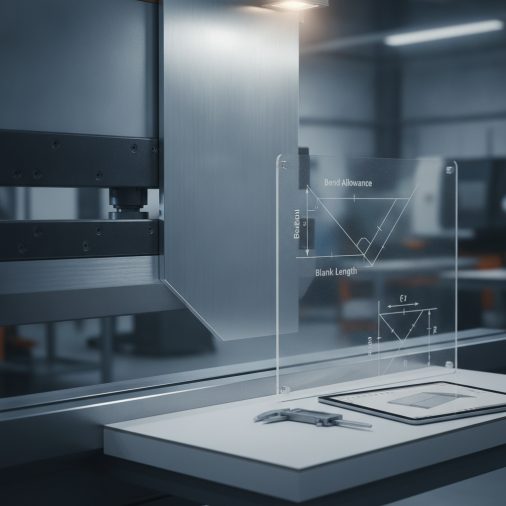
Accurate flat blank length is the foundation of every successful sheet metal bend — cut the blank too short and the finished part falls out of tolerance; cut it too long and you waste material and rework time. This metal bending calculator uses the industry-standard K-factor method to compute bend allowance, bend deduction, outside setback, and total flat blank length for a single bend, giving fabricators, engineers, and hobbyists a reliable starting point before the first piece of stock ever touches a press brake or box-and-pan brake.
Metal Bending Calculator: Bend Allowance, Deduction & Blank Length
Calculate bend allowance, bend deduction, outside setback, and total flat blank length for sheet metal bending operations using K-factor and material thickness.
How to Use This Calculator
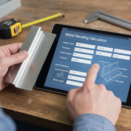
Follow these steps to get accurate bending results:
- Select your unit system — choose inches or millimetres; all inputs and outputs will use that unit.
- Enter material thickness — the measured gauge thickness of your sheet or plate.
- Enter the inside bend radius — the radius of the punch tip or the desired inside radius of the finished bend.
- Enter the bend angle — the included angle through which the material is bent (e.g., 90° for a right-angle bend).
- Select a K-factor — choose the preset that best matches your material and tooling, or enter a custom value. Soft materials bent with a large radius use a lower K-factor; hard materials or tight radii use a higher one.
- Enter Leg 1 and Leg 2 lengths — the desired finished outside dimensions of each flat leg measured from the apex of the bend.
- Read the results: bend allowance, bend deduction, outside setback, and total flat blank length.
Understanding the Calculator Inputs
Unit System: Select Inches for imperial work or Millimetres for metric. All inputs must be entered in the chosen unit; the results will be returned in the same unit. Do not mix units — for example, do not enter thickness in millimetres while using the inches setting.
Material Thickness: Measure the actual thickness of your sheet with calipers rather than relying on nominal gauge values, which can vary by material and standard. For mild steel 18-gauge is nominally 0.0478 in (1.214 mm), but always verify. Accurate thickness is the single most important input because it appears in every formula.
Inside Bend Radius: This is the radius at the inside surface of the bend — the side touching the punch tip. It is not the outside radius or the centerline radius. For air bending on a press brake, the inside radius is approximately 16% of the die opening width as a rule of thumb, but the actual value depends on tooling and material springback. Measure or obtain this from your tooling data sheet.
Bend Angle: Enter the included bend angle — the angle through which the material is actually bent. A 90° bend produces a right angle. A 45° bend produces a 135° included angle in the finished part. If your drawing calls out the included angle of the finished part (e.g., 135°), subtract it from 180° to get the bend angle (180° − 135° = 45°). The calculator accepts values from 1° to 179°.
K-Factor Preset: The K-factor (K) represents the ratio of the neutral axis location to the material thickness. It ranges from 0.25 to 0.50. Use 0.25 for very soft materials (soft copper, soft aluminium) bent over a large radius. Use 0.33 for most mild steel and aluminium in typical fabrication. Use 0.38–0.42 for harder alloys or tighter radii. Use 0.50 when the neutral axis sits at the exact mid-thickness, which is theoretically the maximum. When in doubt, 0.33 is the most commonly used default for mild steel.
Leg 1 and Leg 2 Lengths: Enter the desired outside finished dimensions of each flat leg, measured from the outside mold line (the apex of the outside bend corner) to the end of the part. These are the dimensions you would see on a typical fabrication drawing. Both legs must be greater than the outside setback value, or the geometry is physically impossible.
Understanding Your Results
Bend Allowance (BA): The arc length of the neutral axis through the bend zone. This is the amount of material consumed by the bend itself. It is always a positive number and increases with larger radii, larger angles, and higher K-factors.
Outside Setback (OSSB): The distance from the outside mold line (the theoretical sharp corner on the outside of the bend) to the tangent point where the bend begins or ends. It is used to locate the bend line on the flat blank and to calculate bend deduction. OSSB increases with larger radii, greater material thickness, and larger bend angles.
Bend Deduction (BD): The total amount subtracted from the sum of the two outside leg dimensions to obtain the flat blank length. BD = 2 × OSSB − BA. A positive BD means you subtract from the sum of the legs; a negative BD (rare, only at very small angles with large radii) would mean you add. Most practical bends produce a positive BD.
Flat Leg 1 and Flat Leg 2: Each leg dimension reduced by one OSSB, giving the flat distance from the end of the blank to the start of the bend zone. These are the distances you would mark on the flat blank to locate the bend line.
Total Flat Blank Length: The overall length of flat stock required to produce the finished bent part. This is the primary output most fabricators need for cutting stock to length before bending. It equals Flat Leg 1 + Flat Leg 2 + Bend Allowance.
Calculation Formulas Explained
All formulas follow the K-factor neutral axis method, which is the standard approach used in sheet metal fabrication and described in the Machinery’s Handbook and ASME standards.
Bend Allowance (BA): BA = π × (bend_angle / 180) × (R + K × t) — where R is the inside bend radius, K is the K-factor, and t is the material thickness. The term (R + K × t) is the neutral axis radius. Multiplying by the radian angle gives the arc length along the neutral axis.
Outside Setback (OSSB): OSSB = (R + t) × tan(bend_angle / 2) — the outside radius is (R + t). The tangent of half the bend angle converts that radius to the horizontal setback distance from the mold line to the tangent point. This is a basic trigonometric relationship for a circular arc.
Bend Deduction (BD): BD = 2 × OSSB − BA — subtracting the bend allowance from twice the outside setback gives the total deduction. This is the shortcut used when working from outside dimensions on a drawing.
Total Flat Blank Length: L = (Leg1 − OSSB) + (Leg2 − OSSB) + BA — each leg is reduced by one OSSB to find the flat portion, and the bend allowance is added for the curved zone. This is algebraically equivalent to L = Leg1 + Leg2 − BD.
All angle conversions use the factor π/180 = 3.14159265/180 to convert degrees to radians, as required by trigonometric functions.
Worked Example
Scenario: You need to bend a piece of 11-gauge mild steel (thickness = 0.120 in) to a 90° angle. The press brake punch has a 0.125 in tip radius. The finished part must have a 2.500 in outside leg on one side and a 1.500 in outside leg on the other. You are using a standard K-factor of 0.33.
- Inputs: t = 0.120 in, R = 0.125 in, angle = 90°, K = 0.33, Leg1 = 2.500 in, Leg2 = 1.500 in.
- Bend Allowance: BA = π × (90/180) × (0.125 + 0.33 × 0.120) = 3.14159265 × 0.5 × (0.125 + 0.0396) = 1.5708 × 0.1646 = 0.2585 in
- Outside Setback: OSSB = (0.125 + 0.120) × tan(45°) = 0.245 × 1.0000 = 0.2450 in
- Bend Deduction: BD = 2 × 0.2450 − 0.2585 = 0.4900 − 0.2585 = 0.2315 in
- Flat Leg 1: 2.500 − 0.2450 = 2.2550 in
- Flat Leg 2: 1.500 − 0.2450 = 1.2550 in
- Total Flat Blank Length: 2.2550 + 1.2550 + 0.2585 = 3.7685 in
Cut your flat blank to 3.7685 in, mark the bend line at 2.2550 in from one end (or 1.2550 in from the other end), and bend to 90°. The finished outside legs should measure 2.500 in and 1.500 in respectively.
How to Interpret the Results
The Total Flat Blank Length is your cut-to-length dimension. Add a small scrap allowance (typically 0.010–0.030 in / 0.25–0.75 mm) on your first prototype piece to account for springback variation and tooling wear, then verify the finished dimensions before cutting production stock.
If the Flat Leg values come out negative, your leg dimension is smaller than the outside setback, which means the geometry is impossible — the bend zone would extend beyond the end of the part. Increase the leg length or reduce the inside bend radius.
A Bend Deduction larger than expected usually signals that the inside bend radius is too tight relative to the material thickness. A radius-to-thickness ratio (R/t) below 1.0 can cause cracking in many materials; consult your material’s minimum bend radius specification before proceeding.
Compare your calculated blank length against a test bend. If the finished legs are consistently long, your effective K-factor is lower than selected; if they are consistently short, increase the K-factor. Iterating K-factor from test bends is standard practice in production sheet metal shops.
Common Mistakes to Avoid
- Confusing bend angle with included angle: A part drawn with a 135° included angle requires a 45° bend angle input (180° − 135° = 45°). Entering 135° will produce a wildly incorrect blank length.
- Using nominal gauge thickness: Nominal gauge values are averages. Always measure actual thickness with calipers. A 0.005 in error in thickness on a tight-radius bend can shift the blank length by more than 0.010 in.
- Assuming the inside radius equals the punch tip radius: In air bending, the actual inside radius is determined by the die opening and material properties, not just the punch tip. Measure the actual inside radius on a test bend.
- Applying a single K-factor to all materials: Aluminium, stainless steel, and mild steel have different K-factors even at the same thickness and radius. Use material-specific values when tight tolerances are required.
- Forgetting springback: This calculator computes the geometry of the bent part at the target angle. Springback means you must overbend slightly to achieve the target angle after the press releases. The amount of overbend depends on material yield strength and is not included in this calculation.
- Measuring leg length from the wrong reference: Leg lengths must be measured from the outside mold line (the theoretical sharp outside corner), not from the tangent point or the inside surface. Check your drawing’s dimensioning standard before entering values.
Limitations and Important Notes
This calculator is designed for single-bend, constant-radius sheet metal bending using the K-factor neutral axis method. It does not account for multi-bend parts, compound bends, roll bending, rotary bending, or tube bending, which require different geometric models.
The K-factor presets are industry-standard approximations. Actual K-factor values vary with material alloy, temper, grain direction, tooling geometry, lubrication, and bending method (air bending vs. bottoming vs. coining). For critical structural or aerospace parts, derive K-factor empirically from test bends on the actual material and tooling to be used in production.
Springback is not modelled. The calculator assumes the material holds the bent angle exactly. In practice, elastic recovery causes the part to open slightly after the press releases; the overbend angle required to compensate must be determined by testing.
Results are mathematical planning estimates only. Always verify with a prototype bend before cutting production stock. This tool does not constitute engineering certification or approval for any structural application. For structural sheet metal work, consult a qualified engineer and applicable codes.
Frequently Asked Questions
What is K-factor in sheet metal bending and how do I choose the right value?
The K-factor is a dimensionless ratio that describes where the neutral axis sits within the material thickness during bending. A K-factor of 0.5 means the neutral axis is at the exact mid-thickness; lower values mean it has shifted toward the inside of the bend due to compression. For most mild steel fabrication work, 0.33 is the standard default. Use 0.25 for very soft, ductile materials like annealed copper or soft aluminium bent over a generous radius. Use 0.38–0.42 for harder alloys or when the inside radius is less than the material thickness. The most reliable approach is to bend a test piece, measure the actual flat blank consumed, back-calculate the K-factor, and use that value for the production run.
What is the difference between bend allowance and bend deduction?
Bend allowance (BA) is the arc length of material along the neutral axis that is consumed by the bend zone — it is the physical length of curved material. Bend deduction (BD) is a shortcut number used when working from outside dimensions: it is the total amount you subtract from the sum of the two outside leg dimensions to get the flat blank length. BD equals 2 × OSSB − BA. Fabricators who dimension parts from outside surfaces use BD directly; those who work from inside surfaces or mold lines use BA. Both methods give the same flat blank length when applied correctly.
Why does my finished part come out longer or shorter than the calculator predicts?
The most common causes are an incorrect K-factor, an inaccurate inside bend radius input, or springback. If your finished legs are consistently too long, your effective K-factor is lower than the value you selected — try 0.25 or 0.33. If the legs are too short, increase the K-factor toward 0.42 or 0.50. If the angle is off rather than the leg length, springback is the likely culprit; the calculator does not model springback. Also verify that you are measuring the actual inside radius of the bend (from a test piece) rather than assuming it equals the punch tip radius, especially in air bending where the die opening controls the radius.
Can I use this calculator for aluminium sheet metal?
Yes. Enter the actual measured thickness and inside bend radius for your aluminium stock, then select the K-factor that matches the alloy and temper. Soft aluminium alloys like 3003-H14 typically use K = 0.33, while harder alloys like 6061-T6 may require K = 0.38–0.42 and have a larger minimum bend radius to avoid cracking. Always check the minimum bend radius specification for your specific alloy and temper before bending, as 6061-T6 in particular is prone to cracking at tight radii. If you are also welding the aluminium after bending, the heat-affected zone will change the material properties near the weld.
What is outside setback (OSSB) and why does it matter?
Outside setback is the distance from the theoretical sharp outside corner of the bend (called the mold line) to the point where the flat portion of the material ends and the curved bend zone begins. It matters because it tells you exactly where to mark the bend line on your flat blank. If you mark the bend line at the wrong location, the finished leg dimensions will be off even if the blank length is correct. OSSB also appears in the bend deduction formula, so an error in OSSB propagates into the blank length calculation.
Does this calculator work for tube or pipe bending?
No. Tube and pipe bending involve different geometry, including wall thinning on the outside of the bend, potential ovalization of the cross-section, and a different neutral axis model that accounts for the hollow section. This calculator is specifically designed for flat sheet and plate bending on a press brake or similar tooling. For tube bending calculations, a dedicated tube bending calculator that accounts for CLR (centerline radius), wall factor, and degree of bend is required.
How does the bend angle input relate to what I see on a fabrication drawing?
Fabrication drawings typically dimension the included angle of the finished part — for example, a right-angle bracket is drawn as 90°. However, the bend angle input in this calculator is the angle through which the material is bent, which equals 180° minus the included angle for bends less than 180°. A 90° included angle requires a 90° bend angle input (180° − 90° = 90°, which happens to be the same). A 135° included angle requires a 45° bend angle input (180° − 135° = 45°). Always confirm which convention your drawing uses before entering the value.
What minimum inside bend radius should I use to avoid cracking?
Minimum bend radius depends on the material, alloy, temper, thickness, and grain direction. As a general guideline, mild steel can typically be bent to a radius equal to its thickness (R/t = 1) without cracking when bending across the grain. Bending parallel to the rolling direction requires a larger radius. Hard or high-strength alloys may require R/t ratios of 2–4 or more. Consult the material manufacturer’s data sheet for the specific minimum bend radius. If you are working with sheet metal that will later be welded, MIG welding sheet metal techniques can help you plan the post-bend joining process without introducing distortion near the bend zone.