Accurate flat blank sizing is the foundation of every successful sheet metal bend — get it wrong and your finished part will be too long, too short, or misaligned at the flange. This bending sheet metal calculator uses the industry-standard K-factor method to compute bend allowance, bend deduction, outside setback, and total flat blank length in seconds. Whether you are working with mild steel, aluminium, or stainless steel on a press brake or box-and-pan brake, simply enter your material thickness, inside bend radius, bend angle, and flange dimensions to get precise, shop-ready numbers every time.
Bending Sheet Metal Calculator: Bend Allowance, Deduction & Blank Size
Calculate bend allowance, bend deduction, outside setback, and flat blank length for sheet metal bending operations using the K-factor method.
How to Use This Calculator
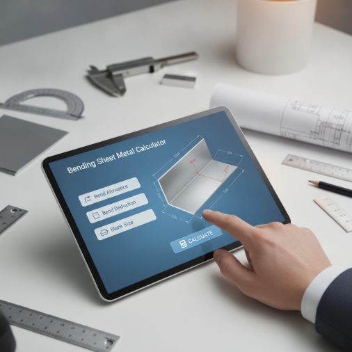
Follow these steps to get accurate results from the calculator:
- Select your unit system — choose inches or millimetres; all inputs and outputs will use the same unit.
- Enter material thickness (T) — measure the actual gauge thickness with calipers, not the nominal gauge value.
- Enter inside bend radius (R) — this is the radius at the inside surface of the bend, typically equal to the punch nose radius on a press brake.
- Enter bend angle — input the included bend angle in degrees (e.g., 90° for a right-angle bend).
- Select a K-factor — choose the preset that matches your material and tooling, or enter a custom value. Soft materials bent with a large radius use lower K-factors; hard materials or sharp bends use higher values.
- Enter Flange A and Flange B lengths — these are the flat portions of each leg measured from the tangent point of the bend (the mold line), not from the outside edge.
- Read your results — the calculator returns bend allowance, bend deduction, outside setback, and total flat blank length ready to mark out on your stock.
Understanding the Calculator Inputs
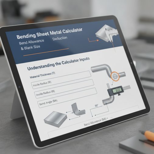
Unit System: Select Inches or Millimetres. All inputs must be entered in the chosen unit; the results will be returned in the same unit. Mixing units is the single most common source of blank-length errors on the shop floor.
Material Thickness (T): Enter the actual measured thickness of your sheet or plate. For sheet metal, always verify with calipers — nominal gauge values can differ from actual thickness by several thousandths of an inch. Common sheet metal thicknesses range from 0.020 in (0.5 mm) for light-gauge work up to 0.250 in (6.35 mm) for heavier plate bending.
Inside Bend Radius (R): This is the radius measured at the inside (concave) surface of the bend. On a press brake it is typically equal to the punch nose radius. A general rule of thumb is to use a minimum inside radius equal to the material thickness for mild steel; harder materials require larger radii to avoid cracking. If you are planning to join bent parts afterward, understanding MIG welding sheet metal techniques will help you plan flange lengths that leave adequate weld access.
Bend Angle: Enter the included angle of the bend in degrees — the angle between the two flanges as measured on the inside of the part. A 90° entry produces a right-angle bend. Note that this is not the complementary angle (sometimes called the bend angle on older press brake controls that display the angle of punch travel).
K-Factor: The K-factor (K) represents the ratio of the neutral axis location to the material thickness. It accounts for the fact that the neutral axis shifts toward the inside of the bend during forming. Use 0.33 for soft aluminium or copper with generous radii, 0.38 for semi-hard alloys, 0.42 for standard mild steel (the most common default), and 0.50 for very hard materials or bends where R/T is less than 1. For critical production work, derive your K-factor empirically by bending a test piece and back-calculating from the measured blank length.
Flange A and Flange B: Enter the finished flat length of each leg, measured from the tangent point (also called the mold line or bend tangent line) to the end of the part — not from the outside corner. If you are designing a simple L-bracket with a 1.5 in vertical leg and a 2.0 in horizontal base, Flange A = 1.5 in and Flange B = 2.0 in.
Understanding Your Results
Bend Allowance (BA): The arc length of the neutral axis through the bend zone. This is the amount of material consumed by the bend itself. It is added to the two flange lengths to obtain the total flat blank length. A larger radius or a higher K-factor increases the bend allowance.
Outside Setback (OSSB): The distance from the tangent point of the bend to the outside corner of the part. It is used when laying out bend lines on a flat blank using the outside dimensions of the finished part rather than the flange (mold-line) dimensions. OSSB increases with both bend angle and material thickness.
Bend Deduction (BD): The amount subtracted from the sum of the two outside flange dimensions to obtain the flat blank length. BD = 2 × OSSB − BA. This value is used in the alternative outside-dimension layout method. A positive BD means material is consumed; for very large radii and shallow angles BD can approach zero.
Flat Blank Length: The total length of flat stock required to produce the bent part. This is the primary output for cutting your blank to size before bending. It equals Flange A + Flange B + Bend Allowance.
Neutral Axis Radius: The radius at which the neutral axis sits inside the material cross-section, equal to R + K × T. This intermediate value confirms the K-factor is being applied correctly and is useful for manual verification.
R/T Ratio: The ratio of inside bend radius to material thickness. Values below 1 indicate a sharp bend that risks cracking, especially in hard alloys. Values above 4–6 are considered air-bend territory where springback becomes significant. This ratio helps you select the correct K-factor and assess whether your tooling is appropriate for the material.
Calculation Formulas Explained
All formulas are based on the K-factor neutral axis method, which is the standard approach used in DIN 6935, ASME, and most CAD/CAM sheet metal modules.
Bend Allowance (BA): BA = (π × (R + K × T) × A) / 180 — This is the arc length formula. The neutral axis sits at radius (R + K×T) from the centre of curvature. Multiplying by the bend angle A (in degrees) and dividing by 180 converts the formula from a semicircle to the actual arc fraction. π is approximated as 3.14159265.
Outside Setback (OSSB): OSSB = (R + T) × tan(A/2) — The outside setback is a trigonometric relationship between the outside radius (R + T) and half the bend angle. It represents the horizontal distance from the tangent point to the apex of the outside corner.
Bend Deduction (BD): BD = 2 × OSSB − BA — Bend deduction is derived directly from the relationship between the outside-dimension layout method and the mold-line method. It equals twice the outside setback minus the bend allowance.
Flat Blank Length: Blank = Flange A + Flange B + BA — The simplest and most direct formula: the two flat legs plus the material consumed in the bend arc. Flange lengths here are mold-line dimensions (measured to the tangent point, not the outside corner).
Assumptions: The formulas assume a single bend, uniform material thickness, and that the K-factor is constant through the bend. They do not account for springback, material anisotropy, or work-hardening effects beyond what the K-factor approximates.
Worked Example
Scenario: You need to bend a 16-gauge mild steel sheet (T = 0.060 in) to make an L-bracket with a 1.500 in vertical flange (Flange A) and a 2.000 in horizontal flange (Flange B), bent at 90°. Your press brake punch has a 0.062 in nose radius (R = 0.062 in). You select the standard mild steel K-factor of 0.42.
Step 1 — Neutral Axis Radius: R + K × T = 0.062 + 0.42 × 0.060 = 0.062 + 0.0252 = 0.0872 in
Step 2 — Bend Allowance: BA = (π × 0.0872 × 90) / 180 = (3.14159265 × 0.0872 × 90) / 180 = 24.6488 / 180 = 0.1369 in
Step 3 — Outside Setback: OSSB = (0.062 + 0.060) × tan(45°) = 0.122 × 1.0000 = 0.1220 in
Step 4 — Bend Deduction: BD = 2 × 0.1220 − 0.1369 = 0.2440 − 0.1369 = 0.1071 in
Step 5 — Flat Blank Length: Blank = 1.500 + 2.000 + 0.1369 = 3.6369 in
Cut your blank to 3.637 in (rounded to three decimal places), mark the bend line at 1.500 in from one end (mold-line dimension), and the finished part will have the correct 1.500 in and 2.000 in flanges after bending. If you plan to weld this bracket into an assembly, review welding sheet metal without burning through to protect the thin flanges during joining.
How to Interpret the Results
R/T Ratio guidance: An R/T ratio below 1 signals a sharp bend. For mild steel this is generally acceptable, but for high-strength steel, stainless, or hard aluminium alloys it risks cracking on the outside surface of the bend. If your R/T is below 1, increase the punch nose radius or anneal the material before bending.
Bend Allowance vs. Bend Deduction: Use Bend Allowance when your drawing dimensions are mold-line (tangent-point) dimensions. Use Bend Deduction when your drawing dimensions are outside dimensions measured to the outside corner of the part. Both methods give the same flat blank length when applied correctly — mixing them is a common source of error.
K-factor sensitivity: A K-factor error of ±0.05 on a 90° bend in 0.060 in material changes the blank length by roughly ±0.005 in — negligible for most fabrication. On thicker plate (0.250 in and above) or multi-bend parts, K-factor errors accumulate and can cause significant dimensional errors. Always validate with a test bend on production material before committing a full batch.
Springback: The calculator does not account for springback. After releasing the press brake, elastic recovery causes the bend angle to open slightly. For mild steel at 90°, overbend by approximately 1–3°; for stainless steel or aluminium, overbend by 3–8°. Adjust your press brake stop accordingly.
Common Mistakes to Avoid
- Measuring outside dimensions as flange lengths: Flange A and Flange B must be mold-line dimensions (to the tangent point), not outside dimensions. Using outside dimensions without subtracting the OSSB will produce a blank that is too long.
- Using nominal gauge instead of measured thickness: Nominal 16-gauge mild steel is 0.0598 in, but actual coil thickness can vary by ±0.003 in. Always measure with calipers and use the actual value.
- Confusing included angle with bend angle on the press brake: Some older press brake controls display the punch travel angle (complementary angle). A 90° included bend requires 90° of punch travel from vertical — confirm your machine’s convention before setting up.
- Applying the wrong K-factor for the material: Using the mild steel default (0.42) for 5052-H32 aluminium will underestimate the blank length. Soft aluminium typically uses 0.33–0.38.
- Ignoring grain direction: Bending perpendicular to the rolling direction (across the grain) requires a smaller minimum radius than bending parallel to it. The calculator does not account for grain direction — always orient critical bends across the grain when possible.
- Forgetting to account for multiple bends: This calculator handles one bend at a time. For parts with two or more bends, calculate each bend separately and sum the bend allowances, then add all flange lengths.
Limitations and Important Notes
This calculator applies the K-factor neutral axis method and is intended as a planning and estimating tool. Results are mathematically accurate given the inputs and assumptions stated, but real-world blank lengths may differ due to: material springback (not modelled), variation in actual K-factor caused by tooling wear or lubrication, non-uniform material thickness, work-hardening during forming, and operator-to-operator variation in bend setup. The calculator handles only single, simple bends — compound bends, hemming, coining, and embossing require additional calculations. It does not account for grain direction, anisotropy, or temperature effects. Always produce a test bend on scrap material from the same coil before cutting production blanks. This tool does not constitute engineering advice; for structural or safety-critical applications, consult a qualified mechanical engineer and refer to applicable standards such as ASME Y14.5 or DIN 6935.
Frequently Asked Questions
What is the K-factor in sheet metal bending and how do I choose the right value?
The K-factor (K) is a dimensionless ratio that describes where the neutral axis sits within the material thickness during bending. A K-factor of 0.5 means the neutral axis is exactly at the mid-thickness; values below 0.5 mean it has shifted toward the inside of the bend due to compression. In practice, use 0.33 for soft materials (soft aluminium, copper) with large radii (R/T > 3), 0.38 for semi-hard alloys, 0.42 for standard mild steel (the most widely used default), and 0.50 for very hard materials or sharp bends where R/T < 1. For the most accurate results on production runs, bend a test piece, measure the actual blank consumption, and back-calculate K = (BA × 180 / (π × A) − R) / T.
What is the difference between bend allowance and bend deduction?
Bend allowance (BA) is the arc length of material consumed in the bend zone, measured along the neutral axis. It is added to the mold-line flange lengths to get the flat blank length. Bend deduction (BD) is the amount subtracted from the sum of the outside flange dimensions (measured to the outside corner) to get the flat blank length. Both methods produce the same flat blank length — they are simply two different starting-dimension conventions. Use bend allowance when your drawing calls out dimensions to the tangent point; use bend deduction when dimensions are to the outside corner. Mixing the two conventions without adjustment is one of the most common causes of incorrect blank lengths.
How do I calculate the flat blank length for a part with multiple bends?
For a part with multiple bends, calculate the bend allowance for each bend individually using this calculator, then sum all the flat flange lengths and all the bend allowances. For example, a U-channel with two 90° bends has three flat sections (two flanges and a web) and two bend allowances. Flat blank = Flange 1 + BA1 + Web + BA2 + Flange 2. Each bend may have a different radius, angle, or K-factor, so calculate them separately. Cumulative errors from K-factor approximation become more significant with each additional bend, making test bends especially important for multi-bend parts.
Why does my finished part come out longer or shorter than the calculated blank length?
The most common causes are: using the wrong K-factor for your specific material and tooling combination; measuring flange lengths to the outside corner instead of the tangent point; using nominal gauge thickness instead of the actual measured thickness; and springback causing the bend angle to differ from the intended angle, which changes the effective flange lengths. Additionally, worn tooling, inconsistent lubrication, and variation in material hardness across a coil all shift the effective K-factor. Run a test bend, measure the actual blank consumption, and adjust your K-factor input until the calculator matches your real-world results before committing to production quantities.
What is the minimum inside bend radius for sheet metal?
The minimum inside bend radius depends on the material type, temper, thickness, and grain direction. As a general starting point, mild steel can be bent to a minimum radius of approximately 0.5× to 1× the material thickness; 5052-H32 aluminium requires roughly 1× to 2× thickness; 6061-T6 aluminium requires 3× to 6× thickness due to its brittleness; and stainless steel (304) typically requires 1× to 2× thickness. Bending parallel to the rolling direction (with the grain) requires a larger minimum radius than bending across the grain. Going below the minimum radius causes cracking on the outside surface of the bend. If you are working with thin automotive panels, welding automotive sheet metal resources can help you plan flanges that survive both bending and subsequent joining operations.
Does the calculator account for springback?
No — springback is not included in the bend allowance or blank length calculations. Springback is the elastic recovery that causes the bend angle to open slightly after the press brake releases. The amount of springback depends on the material’s yield strength, elastic modulus, thickness, and bend radius. Mild steel at 90° typically springs back 1–3°; stainless steel and aluminium can spring back 3–10° or more. To compensate, overbend the part by the expected springback angle. Some press brake CNC controllers have built-in springback compensation tables; for manual brakes, determine the overbend angle empirically with test bends on the production material.
Can I use this calculator for tube or pipe bending?
No — this calculator is designed specifically for sheet and plate bending on a press brake or box-and-pan brake. Tube and pipe bending involves different geometry (the cross-section can ovalize), different neutral axis behaviour, and additional factors such as wall thinning, mandrel use, and bend-to-bend spacing. The K-factor neutral axis method used here does not apply directly to tube bending. Use a dedicated tube bending calculator or refer to manufacturer-supplied bend data for your specific tube bender and die set.
How does material thickness affect the bend deduction?
Thicker material increases the outside setback (OSSB) because the outside radius (R + T) grows with thickness, pushing the outside corner further from the tangent point. At the same time, a thicker material with the same inside radius has a lower R/T ratio, which typically shifts the neutral axis inward (lower K-factor) and reduces the bend allowance slightly. The net effect is that bend deduction generally increases with material thickness for a fixed inside radius and bend angle. This is why it is critical to re-calculate blank lengths whenever you switch to a different material thickness, even if the part geometry looks the same. For guidance on working with thicker stock that may later need joining, the welding rod settings chart can help you select appropriate filler parameters.