Weld quality directly affects structural integrity. A joint that looks clean on the surface can still fail under load if a defect is hiding beneath the bead — and in structural, pressure, or load-bearing applications, that failure can be catastrophic.
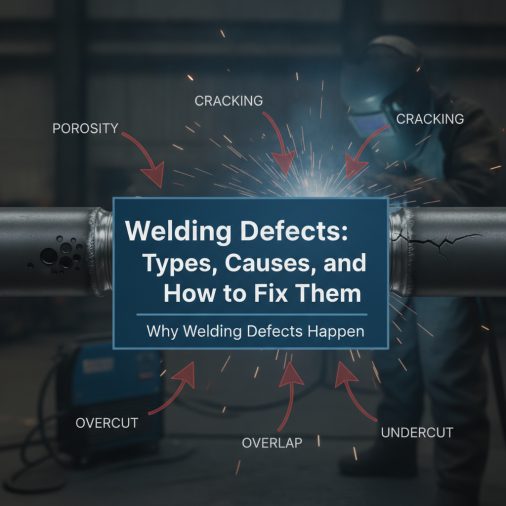
Welding defects are imperfections in a weld joint that reduce its mechanical strength, appearance, or serviceability. Common types include porosity, cracks, undercut, incomplete fusion, overlap, distortion, and spatter. Most defects result from incorrect settings, poor technique, contaminated base metal, or inadequate shielding gas coverage — and most are preventable with proper preparation and parameter control.
Why Welding Defects Happen
Most defects don’t appear randomly. They follow predictable patterns tied to specific process variables.
The main contributing factors are:
– Incorrect heat input — too much or too little amperage for the material thickness
– Poor gas coverage — turbulence, low flow rate, or drafts disrupting the shielding atmosphere
– Contaminated surfaces — oil, rust, mill scale, moisture, or paint on the base metal
– Wrong travel speed — moving too fast produces cold welds; too slow causes burn-through
– Bad joint preparation — incorrect gap, fit-up, or bevel angle
– Welder technique — inconsistent gun angle, arc length, or weave pattern
Understanding which variable caused a defect makes it much easier to fix. Randomly adjusting settings rarely solves the root problem.
The Most Common Welding Defects Explained
Porosity
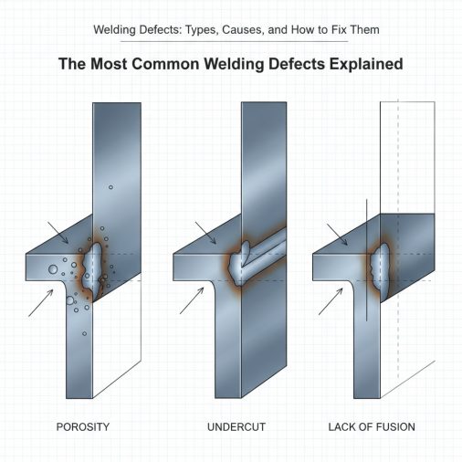
Porosity appears as small holes or voids in the weld metal, caused by gas becoming trapped during solidification. It can appear on the surface (visible pores) or internally (detectable only by X-ray or ultrasonic testing).
Common causes:
– Contaminated base metal (oil, moisture, rust, zinc coating)
– Insufficient shielding gas coverage
– Gas flow rate too low or too high (turbulence draws in atmosphere)
– Damaged or kinked gas hose
– Wet or damp flux
In MIG welding, setting the correct gas flow rate in litres per minute is one of the simplest ways to prevent porosity. Most mild steel MIG applications run well between 10–15 L/min, though windy outdoor conditions may require more.
Fix: Clean base metal thoroughly before welding. Check gas connections for leaks. Shield the work area from drafts. Verify the correct shielding gas for the material being welded.
Cracks
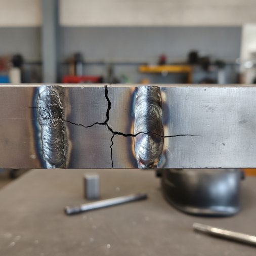
Cracking is one of the most serious defects because cracks propagate under stress. They can be microscopic at first but grow rapidly during service.
Types of cracks:
Crack Type
Location
Primary Cause
Hot crack
In the weld bead
High sulfur/phosphorus content, rapid solidification
Cold crack
HAZ (heat-affected zone)
Hydrogen embrittlement, high carbon steel
Crater crack
End of weld
Not filling the crater before stopping
Lamellar tear
Base metal
High restraint on thick plates with poor through-thickness ductility
Cold cracking (also called hydrogen-induced cracking) is especially common in high-strength steels. Preheating the base metal to 100–200°C before welding significantly reduces the risk.
Fix: Use low-hydrogen electrodes or filler metals. Preheat when required. Control interpass temperature. Fill craters before breaking the arc.
Undercut
Undercut is a groove melted into the base metal along the toes of the weld that is not filled by weld metal. It appears as a notch running parallel to the bead.
It reduces the effective cross-section of the base metal and creates a stress concentration — both dangerous in loaded joints.
Common causes:
– Arc voltage too high
– Travel speed too fast
– Incorrect gun or electrode angle
– Excessive weaving
Fix: Reduce voltage slightly. Slow down travel speed. Adjust electrode angle to direct arc heat toward the weld pool, not the base metal edges.
Incomplete Fusion (Lack of Fusion)
Incomplete fusion means the weld metal did not properly bond with the base metal or with a previous weld pass. The bead appears to sit on top of the metal rather than merging with it.
This defect is particularly deceptive — the weld can look acceptable on the surface while being completely unbonded underneath.
Common causes:
– Heat input too low
– Travel speed too fast
– Incorrect joint preparation
– Arc aimed at solidified weld metal rather than base metal
– Contaminated surfaces
For flux core welders, torch direction (push vs. pull technique) significantly affects fusion depth. Pulling generally provides better penetration in flux core applications.
Fix: Increase amperage or slow travel speed. Ensure proper joint preparation with adequate bevel angles on thick sections. Direct the arc at the leading edge of the puddle.
Incomplete Penetration (Lack of Penetration)
This occurs when the weld does not extend through the full depth of the joint. In a full-penetration weld, you should see root fusion on the back side of the joint.
Common causes:
– Amperage too low
– Root gap too small
– Travel speed too fast
– Electrode or wire diameter too large for the joint
Fix: Increase heat input. Open the root gap slightly. Reduce travel speed. For thick plate, use a proper bevel and root face dimension.
Overlap
Overlap happens when the weld metal rolls over the base metal edge without actually fusing to it. It creates a cold lap at the weld toe that acts as a built-in crack initiator.
Common causes:
– Current too low
– Travel speed too slow
– Incorrect electrode angle
This defect is more common in positional welding, particularly in horizontal and overhead positions, where gravity pulls the molten metal before it properly fuses.
Fix: Increase current slightly. Increase travel speed. Adjust torch angle to direct the arc more precisely into the joint.
Spatter
Spatter consists of metal droplets expelled from the weld pool that land on surrounding surfaces. While often treated as a cosmetic issue, excessive spatter can indicate arc instability and underlying parameter problems.
Heavy spatter in MIG welding is frequently caused by incorrect polarity, voltage too low, wire feed speed too high, or using pure CO₂ gas instead of a mixed gas blend. For a thorough breakdown of spatter causes and solutions, the practical guide to reducing spatter in MIG welding covers specific parameter adjustments.
Fix: Check polarity. Adjust voltage and wire feed speed. Switch to a 75/25 Argon/CO₂ mix if using pure CO₂.
Distortion
Distortion occurs when uneven heating and cooling causes the base metal to warp, bow, or twist out of alignment. It is not a defect in the weld itself but a consequence of weld shrinkage forces acting on the workpiece.
Common causes:
– Excessive heat input
– Poor joint clamping or fixturing
– Incorrect weld sequence on multi-pass or multi-joint structures
– Thin material
Fix: Use intermittent or backstep welding sequences. Clamp workpieces before welding. Balance welds symmetrically on fabricated sections. Use the minimum heat input needed for adequate fusion.
Defect Detection Methods
Not all defects are visible. Serious structural applications require non-destructive testing (NDT) to confirm weld integrity.
Common NDT methods:
Method
What It Detects
Best For
Visual inspection (VT)
Surface defects, geometry
All applications, first check
Dye penetrant testing (PT)
Surface-breaking cracks, porosity
Non-magnetic materials
Magnetic particle testing (MT)
Surface and near-surface cracks
Ferromagnetic steels
Ultrasonic testing (UT)
Internal defects, volumetric flaws
Thick sections, structural welds
Radiographic testing (RT)
Internal porosity, cracks, voids
Pressure vessels, pipework
For most shop fabrication, visual inspection combined with occasional destructive testing of sample welds (bend tests, cross-section macros) provides adequate quality control.
Acceptance Standards for Weld Defects
Not every defect automatically means a rejected weld. Most welding standards define acceptance criteria based on defect type, size, and location.
Common standards that define defect limits include:
– AWS D1.1 — Structural Welding Code (Steel)
– ASME Section IX — Pressure vessels and piping
– ISO 5817 — European standard for fusion-welded joints (Quality levels B, C, D)
– EN 1011 — Welding recommendations for metallic materials
Understanding which standard governs a project is critical before assessing whether a defect is acceptable or requires repair.
Preventing Defects Before They Happen
Prevention is always more efficient than repair. Most weld defects can be controlled at the preparation stage.
Pre-weld checklist:
1. Clean base metal — remove oil, rust, paint, and mill scale within 25mm of the joint
2. Verify correct parameters — amperage, voltage, wire feed speed, and travel speed for the material and thickness
3. Check gas flow rate and verify no leaks in the gas delivery system
4. Confirm joint fit-up — correct root gap, bevel angle, and land dimension
5. Preheat if required — especially on carbon steels above 0.40% carbon equivalent
6. Inspect consumables — check for moisture in flux, correct wire diameter, and undamaged shielding
Flux core welding beginners benefit from reviewing practical setup tips for flux core processes before attempting thicker material, since incorrect settings produce most beginner-level defects.
Repairing Welding Defects
When a defect is found and must be repaired:
1. Mark the defect boundaries — confirm extent by NDT before excavation
2. Grind or gouge out the defective area completely — verify by PT or MT that the defect is fully removed
3. Preheat if required — same preheat as the original weld, sometimes higher
4. Re-weld using qualified procedure and parameters
5. Re-inspect — do not assume the repair weld is defect-free without testing
Incomplete removal of a defect before re-welding is one of the most common repair mistakes. If the original crack or lack of fusion is not fully excavated, the repair weld simply locks the defect in place.
FAQ
What is the most common welding defect?
Porosity is widely considered the most frequently occurring welding defect across all processes. It is primarily caused by shielding gas problems, surface contamination, or moisture in consumables. Because it can form internally without any visible surface indication, porosity is also one of the harder defects to detect without proper NDT methods.
Can welding defects be seen without testing equipment?
Some defects are visible to the naked eye — undercut, overlap, cracks on the surface, and excessive spatter are all detectable by visual inspection. However, internal defects such as porosity, lack of fusion, and subsurface cracks are invisible without methods like ultrasonic testing or radiography. Visual inspection alone is never sufficient for structural or pressure applications.
What causes porosity in flux core welding?
In flux core welding, porosity most often results from contaminated base metal, damaged flux in the wire, incorrect wire stickout distance, or drafts disrupting the shielding atmosphere. Using self-shielded flux core wire outdoors in windy conditions without wind protection is a very common cause. Checking the recommended flux core amperage settings for the wire diameter and material thickness also helps eliminate porosity caused by insufficient heat.
What is the difference between incomplete fusion and incomplete penetration?
Incomplete fusion is a lack of bonding between the weld metal and the base metal (or between weld passes), often occurring at the sidewalls of the joint. Incomplete penetration means the weld root did not fully fuse through the joint depth. Both are serious structural defects, but they have different causes and are found in different locations within the joint.
How does travel speed affect weld defects?
Travel speed directly controls heat input per unit length. Too fast reduces fusion and penetration, leading to incomplete fusion and cold laps. Too slow causes excess heat, increasing the risk of burn-through, distortion, and overlap. Consistent travel speed is one of the most controllable variables a welder has to prevent defects. Most experienced welders adjust speed instinctively based on the puddle behavior rather than relying on a fixed number.
Are welding defects always the welder’s fault?
Not always. Base metal quality, incorrect consumables, equipment calibration issues, and poor joint design all contribute to defect formation independent of welder skill. Contaminated wire spools, incorrect shielding gas supplied by the gas vendor, or a gas regulator delivering inconsistent flow can create porosity even with perfect technique. Good welding practice means checking the full system — not just technique — when defects appear.
What does undercut look like and is it serious?
Undercut appears as a narrow groove or channel cut into the base metal along the edge of the weld bead. It is visible as a depression running parallel to the weld. Severity depends on depth and application — AWS D1.1 permits undercut up to 1mm (1/32 in.) in most static load applications, but any undercut is unacceptable in fatigue-loaded or dynamically stressed joints because it concentrates stress at the weld toe.
Welding defects follow predictable patterns — once you understand what causes each type, most of them become avoidable. Good preparation, correct parameter selection, and consistent technique eliminate the vast majority of defects before the arc is even struck. When defects do appear, treating them as diagnostic information rather than frustration leads to faster, more reliable fixes.