
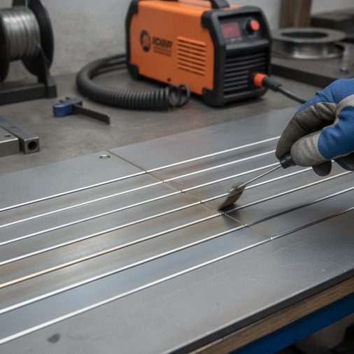
Flat, smooth MIG welds don’t happen by accident. If your beads are sitting high, humping up in the middle, or looking more like a stack of coins than a clean run, something in your setup or technique is off. The good news is that most of the causes are fixable once you know what to look for. This article walks through the key variables — wire feed speed, voltage, travel speed, gun angle, and more — so you can dial in welds that lay flat and look professional.
To get MIG welds to lay flat, increase your voltage slightly, reduce wire feed speed, slow your travel speed, and keep your gun angle between 10–15 degrees push or drag. Flat, wide beads result from proper heat input and correct technique — not just one setting.
Why MIG Welds Hump Up in the First Place
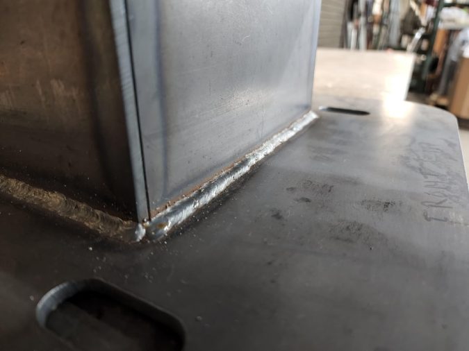
A high, convex bead is almost always a sign of insufficient heat relative to the wire being deposited. When the arc doesn’t have enough energy to properly wet out the puddle, the molten metal piles up instead of spreading flat against the base metal.
The weld pool needs enough heat to flow outward. Think of it like pouring syrup on a cold plate versus a warm one — heat determines how far the material spreads before it freezes, so understanding determine proper weld size practical can make the next step clearer.
The two most common culprits are voltage that’s too low and wire feed speed that’s too high. These two settings work together, and getting their ratio wrong is the fastest way to produce a humped bead.
The Settings That Matter Most
Voltage and Wire Feed Speed Ratio
Voltage controls arc length and heat. Wire feed speed controls how much filler metal enters the puddle. When wire feed speed is too high relative to voltage, you’re stuffing metal into the joint faster than the arc can melt and spread it — the result is a tall, narrow bead.
A practical starting point:
| Material Thickness | Wire Diameter | Voltage (V) | Wire Feed Speed (IPM) |
|---|---|---|---|
| 1/8 in (3mm) | 0.030 in | 17–19 V | 200–250 IPM |
| 3/16 in (5mm) | 0.035 in | 18–21 V | 230–280 IPM |
| 1/4 in (6mm) | 0.035 in | 20–23 V | 260–320 IPM |
| 3/8 in (10mm) | 0.045 in | 22–26 V | 300–380 IPM |
These are starting ranges — always run a test bead on scrap before committing to a joint.
Travel Speed
Moving too fast starves the puddle of heat and produces a narrow, ropy bead. Moving too slow piles up metal and can cause burn-through or excessive spatter.
A flat bead typically requires a moderate, consistent travel speed where the puddle stays ahead of the wire tip by about 3/8 to 1/2 inch. If you’re chasing the puddle, you’re moving too fast. If the puddle is building up behind the tip, slow down slightly or increase voltage.
Gun Angle and Its Effect on Bead Profile
Gun angle has a direct and often underestimated effect on bead shape. The two techniques are:
– Push (forehand): Gun angled 10–15 degrees in the direction of travel. Produces a flatter, wider bead with less penetration. Ideal for thinner material and flat bead appearance.
– Drag (backhand): Gun angled 10–15 degrees away from the direction of travel. Produces a narrower, higher bead with deeper penetration. Better for thicker material.
For flat-laying welds, a slight push angle is generally preferred. It spreads the puddle outward and gives the bead a lower, wider profile.
Avoid excessive angles in either direction. Going past 20–25 degrees introduces porosity, inconsistent penetration, and a bead that wanders.
Work Angle and Joint Position
Work angle — the angle of the gun relative to the joint — affects how the bead sits in the groove or on the surface.
– For a flat butt weld, hold the gun perpendicular to the workpiece (90 degrees).
– For a fillet weld (T-joint or lap joint), split the angle at 45 degrees between the two pieces.
Tilting the gun too far toward one side of a fillet weld causes the bead to roll to that side, creating an uneven, humped profile on one edge. Keeping the work angle centered lets the puddle distribute evenly across both fusion faces.
Shielding Gas Selection and Flow Rate
Shielding gas composition affects bead shape more than most beginners expect.
– 100% CO₂ produces a stiffer arc, deeper penetration, and a slightly more convex bead profile. It’s cheaper but harder to control for flat appearance.
– 75/25 (Argon/CO₂) — also called C25 — produces a softer arc, better puddle control, and a flatter, smoother bead. Many readers compare this with mig welding exhaust pipe settings when they want a more complete answer.
– 90/10 or 85/15 (Argon/CO₂) blends produce even flatter beads with less spatter, often used for thinner gauge material.
Flow rate should typically be set between 15–25 CFH depending on conditions. In a drafty environment, increase flow slightly. Excessive flow (above 30 CFH) can cause turbulence and actually introduce porosity.
Technique Adjustments That Make a Real Difference
Stringer Beads vs. Weave Patterns
A straight stringer bead, when properly set up, will lay flatter than a weave. Weaving spreads heat unevenly and can cause the edges to undercut while the center builds up.
If you need to cover a wider area, use multiple stringer passes rather than a wide weave. Each pass lays flat, and the overlapping passes build width without sacrificing profile.
Consistent Contact Tip-to-Work Distance (CTWD)
CTWD — the distance from the contact tip to the workpiece — directly affects voltage at the arc. Most MIG setups work best with a CTWD of 3/8 to 5/8 inch (roughly 10–15mm).
Getting too close increases heat and can cause burn-back. Getting too far reduces heat and produces a humped, spatter-heavy bead. Keeping this distance consistent throughout the weld is one of the most overlooked fundamentals.
Steady Travel Pace
Inconsistent travel speed is one of the most common causes of uneven bead profiles. Sections where you slowed down will be wider and flatter; sections where you sped up will be narrow and tall.
Practice on scrap until your travel speed feels natural and your arm motion is smooth. Some welders count a rhythm or hum a steady beat to keep pace consistent.
Common Problems and What They Tell You
| Bead Appearance | Likely Cause | Fix |
|---|---|---|
| High, narrow, ropy bead | Voltage too low or WFS too high | Increase voltage or reduce WFS |
| Wide, flat with undercut edges | Voltage too high | Reduce voltage slightly |
| Humped center, flat edges | Travel speed too slow | Increase travel speed |
| Inconsistent height along bead | Inconsistent travel speed or CTWD | Practice steady motion, check gun position |
| Porosity (holes in bead) | Shielding gas issue or contamination | Check gas flow, clean base metal |
| Excessive spatter with high bead | Inductance too low (on inverter machines) | Increase inductance setting if available |
When the Machine Has an Inductance Setting
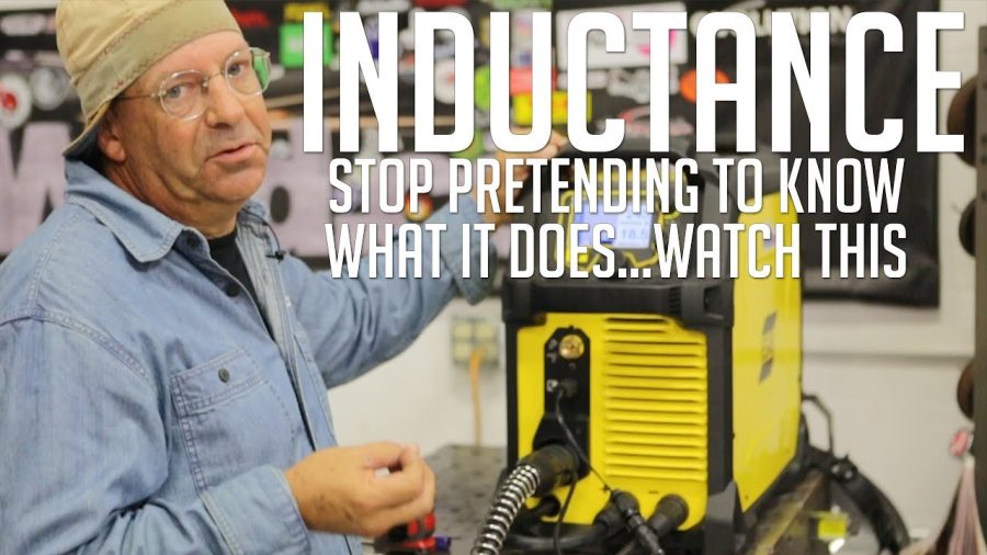
Some modern inverter-based MIG welders include an inductance or arc control adjustment. This setting controls how quickly the arc responds to changes in arc length.
– Higher inductance softens the arc, reduces spatter, and helps the puddle wet out more — producing a flatter bead.
– Lower inductance produces a stiffer, crisper arc with more spatter but faster freeze time.
For flat bead appearance on mild steel, a slightly higher inductance setting is generally beneficial. Lincoln Electric, Miller, and ESAB machines often label this as “arc control” or “inductance” — check your machine’s manual for the specific range.
FAQ
Why does my MIG weld look like a stack of dimes?
A stack-of-dimes appearance in MIG welding usually means you’re moving too fast, your voltage is too low, or both. Unlike TIG welding where that pattern is intentional, in MIG it indicates the puddle isn’t staying fluid long enough to flow flat. Increase voltage slightly and slow your travel speed until the bead smooths out.
Does wire diameter affect how flat a MIG bead lays?
Yes. Larger diameter wire deposits more metal per inch of travel, which can cause a higher bead profile if voltage isn’t increased to match. Thinner wire (0.023 or 0.030 in) is easier to run flat on thin material. Thicker wire (0.035 or 0.045 in) requires higher voltage to achieve the same flat profile on heavier material.
Should I push or pull for a flat MIG weld?
Pushing (forehand technique) generally produces a flatter, wider bead compared to dragging. The push angle directs arc heat forward into the base metal, which helps the puddle spread outward. Use a 10–15 degree push angle for the flattest bead profile. Dragging is better when penetration matters more than appearance.
Can shielding gas really change my bead shape that much?
Absolutely. Switching from 100% CO₂ to a 75/25 Argon/CO₂ mix can noticeably flatten your bead and reduce spatter without changing any other settings. The argon content stabilizes the arc and improves puddle fluidity. If you’re welding mild steel and bead appearance matters, C25 is the standard choice for good reason.
Why does my bead lay flat on scrap but hump up on the actual part?
The most likely cause is a difference in material temperature or cleanliness. Cold or dirty base metal absorbs heat faster, causing the puddle to freeze before it can spread. Preheat thicker material to 200–300°F, clean mill scale and rust from the weld zone, and make sure your scrap test piece is similar in thickness and condition to the actual part.
How do I get a flat bead on vertical MIG welds?
Vertical welding changes the game because gravity works against you. For vertical-up, reduce voltage and wire feed speed by about 10–15% compared to flat position settings, and use a slight weave or upside-down V motion to control the puddle. For vertical-down, travel faster and keep heat input low. Flat-position settings will cause the puddle to sag and drip when welding vertical.
What’s the right contact tip-to-work distance for flat beads?
Keep CTWD between 3/8 and 5/8 inch (10–15mm) for most mild steel MIG applications. A longer stickout reduces heat at the arc and causes humped, spatter-heavy beads. A shorter stickout increases heat and can cause burn-back or excessive penetration. Consistent CTWD throughout the weld is just as important as the distance itself.
Final Thoughts
Flat MIG welds come down to heat balance — enough voltage to wet the puddle out, a wire feed speed that matches it, and a travel pace that keeps everything moving evenly. Get those three variables working together, add a slight push angle, and use C25 gas on mild steel, and the bead profile will take care of itself. Run test beads on scrap every time you change material thickness or switch wire, and adjust from there rather than guessing on the actual joint.


