
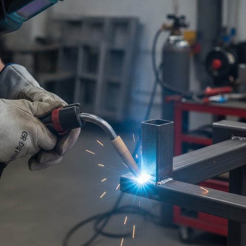
What “RD” Actually Means on a Weld Drawing
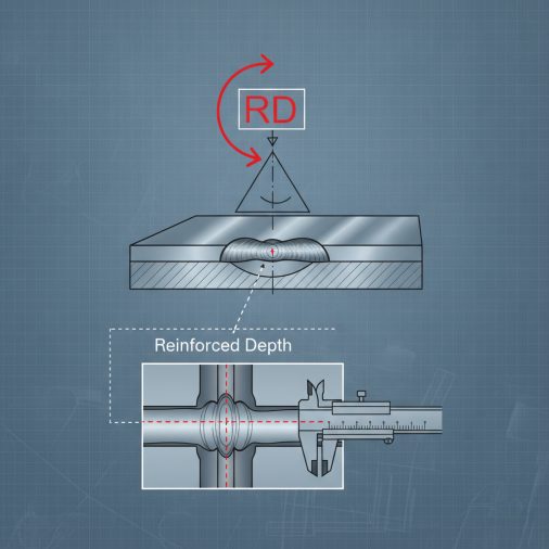
Rounded Weld Profile in MIG Welding
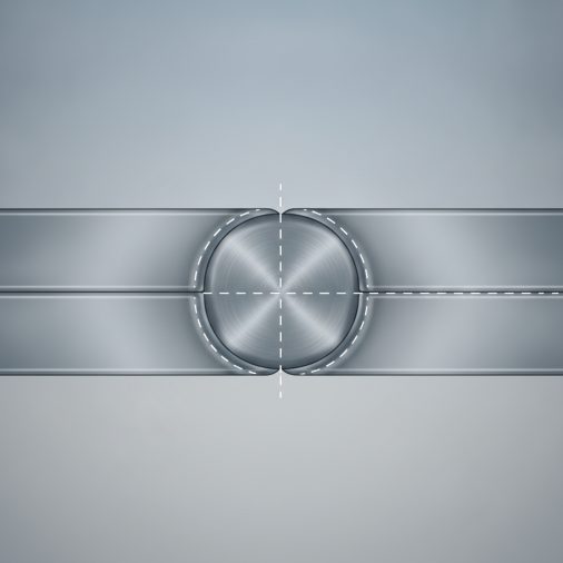
Rotary Drive (RD) MIG Welding Explained
In automated and semi-automated welding systems, RD MIG often refers to a rotary drive MIG setup. This is common in pipe welding, pressure vessel fabrication, and high-production environments. In this configuration, the workpiece or the welding head rotates during the weld pass. The MIG torch remains stationary while the component turns, or in some configurations, a welding head travels around a fixed pipe using a rotary drive mechanism. Key characteristics of rotary drive MIG welding: – Consistent travel speed across the entire weld joint – Reduced operator fatigue and human variation – Better repeatability for production runs – Often paired with wire feeders rated for continuous operation The Lincoln Electric NA-3 or similar automated wire feeders are commonly used in rotary drive MIG setups where weld quality and deposition rate consistency are critical. These systems are generally paired with a constant voltage power source and programmable parameters.How to Achieve a Proper Rounded Bead Profile Manually
If you’re welding to a spec that calls for a rounded contour — not automated, just manual MIG — here’s how to produce it consistently. 1. Set voltage slightly higher than minimum threshold A slightly higher voltage setting produces a wider, more fluid puddle that naturally crowns into a rounded profile. Too low and you get a ropey, narrow bead. 2. Keep travel speed moderate and steady Moving too fast produces a thin, flat bead. Moving too slowly piles up material into an overly convex lump. Aim for a pace where the puddle stays about twice the diameter of the wire being used. 3. Maintain consistent stick-out For most MIG welding, 3/8 to 1/2 inch of contact tip to work distance works well. Inconsistent stick-out directly affects arc voltage and alters your bead profile mid-pass. 4. Use a slight weave or pause at the edges On wider joints, a gentle weave with a brief pause at each side allows the puddle to fill properly and form a smooth, rounded crown rather than a peaked centerline. 5. Check your wire feed speed Too much wire feed relative to voltage creates an overly convex, stubby bead. Balance wire feed speed with voltage to achieve a smooth, consistent rounded profile. If you’re welding in a vertical position, producing a controlled rounded profile becomes significantly harder. welding vertical MIG passes correctly requires specific technique adjustments to keep the profile controlled against gravity.Shielding Gas Considerations for Profile Quality
Gas selection directly influences bead shape and profile. This is often overlooked when trying to hit a specific contour requirement.| Gas Mix | Bead Profile Tendency | Best Use |
|---|---|---|
| 75% Ar / 25% CO₂ (C25) | Slightly convex, smooth | Mild steel general fabrication |
| 100% CO₂ | More convex, rougher surface | Deep penetration, structural |
| 90% Ar / 10% CO₂ | Flatter, wider | Thin material, sheet metal |
| 98% Ar / 2% CO₂ | Very smooth, controlled | Stainless steel applications |
Common Mistakes When a Rounded Profile Is Required
Overbuilding the crown — Some welders add too much material thinking a bigger bead means better reinforcement. Excessive convexity creates stress risers at the toes of the weld and may actually fail inspection if it exceeds the drawing tolerance. Grinding incorrectly — If post-weld grinding is needed to achieve the specified contour, grinding too aggressively removes reinforcement and can introduce grinding marks that become stress concentration points, especially on stainless or high-strength steel. Ignoring joint preparation — A clean, properly fit-up joint is the foundation of any controlled bead profile. Gaps, misalignment, and contamination all disrupt how the puddle flows and solidifies. Confusing contour symbols — On a weld symbol, a flat line indicates a flush finish, a concave arc means a concave contour, and a convex arc means a rounded profile. Misreading these leads to welding the wrong profile from the start.When Root Diameter (RD) Matters in MIG Pipe Welding
In pipe welding documentation, RD sometimes refers to root diameter — the inner bore diameter at the joint. This measurement determines how the root pass is planned and whether a backing ring or open root technique is used. For MIG pipe welding without a backing ring, root diameter tolerances directly affect how much of the root pass penetrates through. A tighter root gap paired with the correct root diameter spec ensures the root bead fuses properly on the inside of the pipe without blowing through. When welding exhaust pipe with a MIG welder, RD awareness becomes practical — thin-wall exhaust tubing has little room for error in root pass penetration, and understanding the root diameter helps you select the right amperage and wire diameter for the job.FAQ
What does RD mean on a MIG weld symbol? RD on a weld symbol typically refers to a rounded or convex contour specification for the finished weld face. It tells the welder that the bead profile should curve outward rather than be flat or concave. In some fabrication documents, RD may also stand for root diameter or rotary drive depending on the application context. What is the difference between a convex and a flush weld profile? A convex (rounded) profile means the weld face curves outward beyond the base metal surface, adding extra reinforcement material. A flush profile means the weld is ground or finished level with the surrounding base metal. Convex profiles are faster to produce but may require grinding if the spec calls for flush. Rounded profiles distribute stress differently than flush ones, which matters in fatigue-loaded applications. Does a rounded bead profile mean a stronger weld? Not necessarily. A rounded profile provides slightly more weld material, which can improve static load capacity. However, excessive convexity can actually reduce fatigue strength by creating stress concentrations at the weld toes. A properly balanced, moderately rounded bead within spec tolerances performs best across most applications. Can wire diameter affect the MIG weld profile? Yes. Smaller diameter wire, such as 0.023 or 0.030 inch, produces a narrower, more focused arc suited for thin material. Larger wire like 0.035 or 0.045 inch deposits more material and creates a wider bead. Matching wire diameter to material thickness and joint size is one of the most effective ways to control bead geometry and profile shape. What causes a MIG weld bead to be too convex or peaked? The most common causes are excessive wire feed speed relative to voltage, insufficient travel speed, or incorrect shielding gas. When wire feed speed is too high compared to the heat input, material piles up faster than the puddle can flow flat. Increasing voltage slightly, reducing wire feed, or increasing travel speed usually corrects a peaked, over-convex bead. How is RD MIG welding used in industrial pipe fabrication? In industrial pipe fabrication, RD MIG typically refers to a rotary drive welding system where the pipe rotates on a positioner while the welding torch remains in a fixed, optimized position. This keeps the welding in the flat or slightly overhead position throughout the pass, improving consistency and reducing defect rates compared to manual all-position welding. Does shielding gas affect whether I can achieve a rounded weld profile? Yes, significantly. Higher argon content mixtures produce smoother, more fluid puddles that flow and crown naturally into a rounded profile. Higher CO₂ content produces more spatter and a stiffer puddle that may be harder to control into a clean rounded contour. For spec work requiring a rounded profile, a C25 (75% argon / 25% CO₂) mix is a reliable starting point on mild steel.Whether you’re reading RD on a weld drawing or setting up a rotary drive MIG system, understanding what the specification actually requires prevents costly rework and failed inspections. Match your gas, wire size, and parameters to the profile requirement, verify your bead contour before final inspection, and don’t confuse a visually appealing bead with one that meets the dimensional callout on the drawing.


