Getting a clean, strong MIG weld isn’t about luck or expensive equipment. Most of the time, it comes down to settings, technique, and preparation — three things you can control on every single weld.
A perfect MIG weld requires correct machine settings (voltage, wire feed speed, and shielding gas), clean base metal, proper travel speed, and a consistent torch angle. The bead should be uniform in width, slightly convex, free of porosity or spatter, and fused smoothly into both sides of the joint without undercutting or overlap.
What a Perfect MIG Weld Actually Looks Like
Before chasing the perfect bead, you need to know what you’re aiming for visually and structurally.
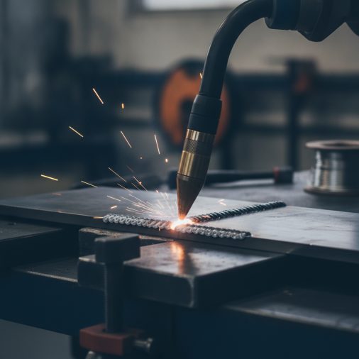
A well-executed MIG weld bead has a consistent ripple pattern, similar to evenly stacked coins. The width should remain steady from start to finish, and the bead shouldn’t sit too tall or spread too flat.
Key visual indicators of a quality weld:
– Uniform bead width — no wide spots or narrow pinches
– Slight crown — a gently rounded top profile, not flat or excessively convex
– Smooth toes — the edges where the weld meets the base metal should blend cleanly, not undercut or roll over
– Minimal spatter — small, scattered spatter spots suggest settings are off
– Consistent color — on mild steel, a straw-to-light-blue tint indicates good heat control
– No porosity — no pinholes or pockmarks in the surface
If you want a deeper breakdown of appearance, understanding what a good MIG weld looks like covers the visual side in detail.
The Foundation: Machine Settings That Matter
Most poor welds trace back to one thing — incorrect machine settings. Getting these right before you strike an arc saves enormous frustration.
Voltage
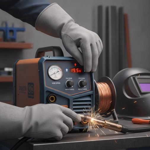
Voltage controls the arc length and bead profile. Too low produces a cold, stubby bead with poor fusion. Too high creates excessive spatter and a flat, wide bead with potential burn-through on thinner material.
A general starting point for mild steel:
Material Thickness
Voltage Range
Wire Diameter
18–22 gauge sheet metal
13–16V
0.023–0.025 in
1/8 in
17–19V
0.030 in
3/16 in
18–21V
0.030–0.035 in
1/4 in
20–23V
0.035 in
3/8 in
22–26V
0.035–0.045 in
Most MIG welders have a chart inside the door panel. Use it as your starting point, then fine-tune from there.
Wire Feed Speed
Wire feed speed (WFS) directly controls amperage and heat input. Too slow causes the wire to burn back toward the tip. Too fast creates a harsh, crackling arc with a lumpy bead.
A smooth, consistent buzzing sound — often described as frying bacon — indicates a dialed-in WFS. A popping, stuttering arc means the speed and voltage are mismatched.
Shielding Gas
For mild steel, a 75% argon / 25% CO₂ mix (C25) is the most common choice. It produces a smooth arc, clean bead appearance, and minimal spatter. Pure CO₂ runs hotter and increases spatter but costs less.
Aluminum requires 100% argon. Stainless steel typically needs a tri-mix or 98% argon / 2% CO₂. understanding whether gas is required for MIG welding explains the role shielding gas plays in weld quality and why flux-core is the alternative.
Preparation Is Half the Battle
No amount of technique compensates for contaminated or improperly fit-up metal. This step is where many welders — including experienced ones — cut corners.
Clean the base metal thoroughly. Mill scale, rust, paint, oil, and galvanizing all introduce contaminants that cause porosity and weak fusion. Use an angle grinder, wire wheel, or flap disc to expose bare metal at least 1–2 inches beyond the weld zone.
Fit-up matters. Gaps that are too wide invite burn-through and poor penetration. Gaps that are too tight on thicker material restrict fusion. A consistent root gap suited to the material thickness sets you up for clean fusion on the first pass.
Tack welds hold everything in place. Small, evenly spaced tacks prevent distortion and keep your joint geometry consistent as you weld.
Torch Angle, Travel Speed, and Direction
These three technique variables have the biggest impact on bead quality during the actual welding process.
Torch Angle
Maintain a work angle of 90° to the joint (perpendicular to the workpiece) and a travel angle of 10–15° in the direction of travel. This is sometimes called a drag or push angle depending on direction.
For most mild steel applications, pushing (forehand welding) produces a flatter, wider bead with better shielding gas coverage. Pulling (backhand) creates a narrower, slightly higher bead with deeper penetration. The push vs. pull debate in MIG welding is worth understanding because the right choice depends on your joint type and material.
Travel Speed
Travel speed controls bead width, penetration depth, and heat input.
– Too slow — excessive buildup, wide bead, risk of burn-through
– Too fast — narrow bead, poor fusion, undercut along the toes
– Correct speed — the weld puddle stays roughly 3/8 to 1/2 inch behind the wire tip
In practice, listen as much as you watch. A steady, smooth arc sound paired with a consistent puddle size means your travel speed is correct.
Weave or Stringer?
Stringer beads (straight line, no weave) are generally stronger and preferred for structural work. Weave patterns are useful when filling wider gaps or covering a broader surface area, but they increase heat input and can cause more distortion.
For thin material especially, stringer beads minimize heat buildup and warping. When welding sheet metal, using proper technique on thin sheet metal makes the difference between a clean repair and a warped mess.
Common Problems and How to Fix Them
Even experienced welders encounter these issues. Identifying the symptom quickly points you toward the right fix.
Problem
Likely Cause
Fix
Porosity (pinholes)
Contamination, bad gas coverage, wrong gas
Clean metal, check gas flow rate (15–25 CFH), fix leaks
Excessive spatter
Voltage too low, wire feed too high, poor gas
Raise voltage slightly, reduce WFS, check gas mix
Undercut
Travel speed too fast, voltage too high
Slow down, reduce voltage
Overlap / cold lap
Travel speed too slow, voltage too low
Speed up, increase voltage
Burn-through
Too much heat on thin material
Reduce voltage and WFS, use stitch/tack technique
Inconsistent bead width
Inconsistent travel speed or shaky hand
Practice steady movement, use both hands when possible
Wire burn-back
Wire feed too slow
Increase wire feed speed
One of the most common issues new welders encounter is porosity, often caused by inadequate shielding gas coverage or contaminated metal. In the field, even a small oil fingerprint on the workpiece can cause visible pinholes in an otherwise clean bead.
Position Welding and Its Effect on Quality
Flat position (1G/1F) is the easiest and most forgiving. The molten puddle naturally stays in place, penetration is consistent, and gravity works with you.
Vertical and overhead positions require adjusted technique and often reduced voltage and wire feed speed to prevent the puddle from sagging. welding vertically with a MIG welder requires specific upward or downward progression depending on material thickness, and getting that technique right directly impacts weld quality.
Horizontal position (2G/2F) is moderately challenging. The torch angle must compensate for gravity pulling the puddle downward, typically requiring a slightly upward work angle.
Gun Distance and Contact Tip Health
The distance from the contact tip to the workpiece (called CTWD — contact tip to work distance) affects arc stability and heat input significantly.
A CTWD of 3/8 to 5/8 inch (roughly 10–15mm) is standard for most wire diameters. Holding the gun too far from the workpiece increases electrical resistance in the wire, reducing effective amperage and producing a cold, inconsistent arc.
Check the contact tip regularly. A worn or partially clogged tip causes arc instability and inconsistent wire feeding, both of which kill bead quality before you even factor in technique.
Keep the liner clean and replace the contact tip at the first sign of poor feeding or arc instability. The Miller Electric Millermatic 211 is a machine commonly recommended for users who want smooth wire feeding out of the box, which reduces tip-related arc issues considerably.
FAQ
What is the ideal travel speed for a perfect MIG weld?
There’s no single number because it depends on material thickness, wire diameter, and heat settings. In practice, aim to keep the puddle about 3/8 to 1/2 inch behind the wire tip, and the bead width roughly 2–3 times the wire diameter. Adjust your speed until the arc sound is smooth and consistent, and the bead ripples appear even.
Why does my MIG weld have porosity even with clean metal?
Porosity with clean metal usually points to a shielding gas problem. Check for leaks in the hose connections, verify your flow rate is between 15–25 CFH, and make sure you’re not welding in a drafty environment that blows the gas away. A damaged or blocked diffuser in the gun can also cause uneven gas coverage even when everything else looks fine.
How do I know if my MIG weld has good penetration?
Surface appearance gives clues — proper fusion shows smooth, blended toes without rollover. But true penetration can only be confirmed destructively through a bend test or cross-section. A well-fused bead typically breaks through the base metal rather than peeling off cleanly at the toes when bent to failure.
What’s the best shielding gas for a clean MIG weld on mild steel?
A 75/25 argon/CO₂ mix (C25) is the standard choice for mild steel MIG welding. It produces a stable arc, minimal spatter, and a smooth bead profile. Pure CO₂ is cheaper and runs hotter but increases spatter noticeably. Some welders use 90/10 or 85/15 mixes for even smoother arc characteristics.
Can wire type affect weld appearance and quality?
Yes, significantly. ER70S-6 wire contains higher levels of silicon and manganese deoxidizers, making it more tolerant of light surface contamination and producing a smoother, shinier bead. ER70S-3 is cleaner-burning but less forgiving on dirty or rusty metal. For general structural and automotive work, ER70S-6 is the most commonly used and reliable choice.
How does travel angle affect the final bead?
Travel angle (the tilt of the gun in the direction of travel) affects shielding gas coverage and bead profile. Angles beyond 20–25° reduce gas coverage and can introduce porosity. Staying within 10–15° provides the best balance of arc stability, bead shape, and fusion. Changing travel angle is one of the quickest ways to influence bead appearance without touching your machine settings.
Does joint type affect what a perfect weld looks like?
Absolutely. A proper fillet weld on a T-joint should form a consistent 45° triangle profile with equal legs. A butt weld should show full fusion across the root with a slight crown. Each joint configuration has its own standard for what constitutes an acceptable and strong weld, so it’s worth learning the expected profile for the joint you’re working on.
Getting a perfect MIG weld consistently comes down to preparation, correct settings, and disciplined technique — not talent. Clean metal, matched voltage and wire feed speed, proper shielding gas, and a steady 10–15° travel angle eliminate the majority of weld defects most people struggle with. Dial in your machine settings on a test piece before welding anything that matters, and treat every weld as a chance to repeat what worked rather than improvise.