MIG welding is one of the most accessible and widely used welding processes available. Whether you’re fabricating a frame, repairing a chassis, or building something from scratch, understanding how the process actually works makes the difference between consistent results and frustrating failures.
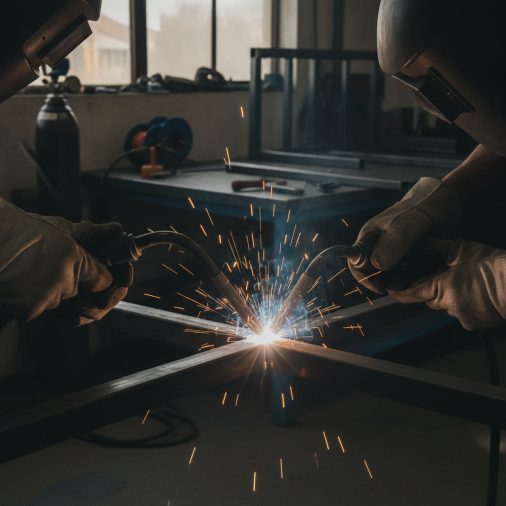
MIG welding — short for Metal Inert Gas welding, formally known as GMAW (Gas Metal Arc Welding) — works by feeding a continuous solid wire electrode through a welding gun while a shielding gas protects the molten weld pool from atmospheric contamination. An electric arc forms between the wire and the base metal, generating heat that melts both the wire and the workpiece to create a fusion weld. It’s fast, relatively easy to learn, and works across a wide range of metals and thicknesses.
How the MIG Welding Arc Actually Works
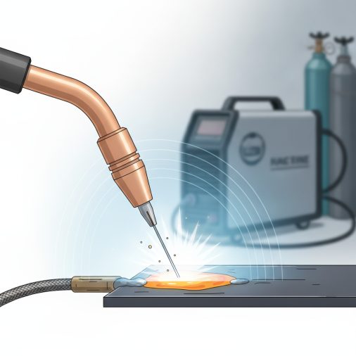
At the core of the MIG process is the electric arc. When the trigger on the welding gun is pulled, wire feeds automatically from a spool through the gun’s contact tip, and the machine creates a circuit between the wire and the grounded workpiece.
The arc generates intense localized heat — typically between 5,000°F and 18,000°F at the arc itself, though the actual weld pool temperature is considerably lower. This heat melts the wire electrode into the base metal, creating a molten puddle that solidifies as the gun moves forward.
The shielding gas flows simultaneously, surrounding the arc and protecting the molten pool from oxygen and nitrogen in the air. Without it, the weld becomes porous and weak. You can read more about whether MIG welding always requires gas depending on the wire type you’re using.
The Four Core Components of a MIG System
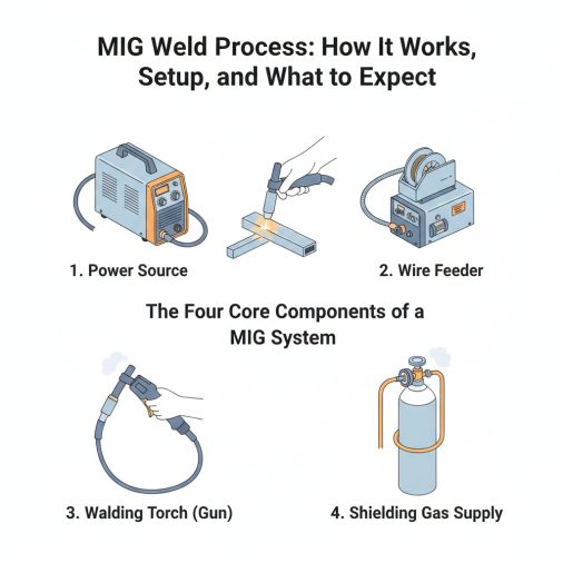
Understanding the equipment helps you troubleshoot problems and dial in better welds. Every MIG setup relies on four main components working together:
Component
Function
Power source
Delivers constant voltage (CV) DC current
Wire feeder
Drives the electrode wire at a set speed
Welding gun
Directs wire, current, and shielding gas to the weld zone
Shielding gas supply
Protects the arc and weld pool from contamination
The power source maintains a steady voltage regardless of arc length fluctuations, which is what makes MIG inherently self-regulating. If the arc length shortens, current increases automatically to compensate.
Shielding Gas Selection and Its Effect on the Weld
Gas choice has a significant impact on arc characteristics, penetration depth, and weld appearance. This is one area where many beginners underestimate the difference between options.
C25 (75% Argon / 25% CO₂) is the most common blend for mild steel. It produces a stable arc, good penetration, and relatively clean welds with minimal spatter. Most hobby and professional work on carbon steel uses this mix.
Pure CO₂ runs hotter and produces deeper penetration but creates more spatter. It’s cheaper and sometimes used in production environments where spatter cleanup is acceptable.
Pure Argon is used for aluminum and other non-ferrous metals. For steel, welding with 100% argon on steel generally produces poor results — the arc becomes unstable and penetration suffers.
For stainless steel, tri-mix gases (typically helium/argon/CO₂) are often used to maintain corrosion resistance and weld quality.
Wire Electrode Types and Diameter Selection
The wire you choose affects deposition rate, penetration, mechanical properties, and how the welder behaves on thinner or thicker stock.
ER70S-6 is the standard all-purpose solid wire for mild steel. The higher silicon and manganese content helps it handle mill scale and slightly contaminated surfaces better than ER70S-3.
ER308L, ER309L, and ER316L are the go-to choices for stainless steel applications. Getting the right wire matters — using standard mild steel wire on stainless steel compromises corrosion resistance and weld integrity.
Wire diameter selection should roughly match material thickness:
– 0.023″ — thin sheet metal under 18 gauge
– 0.030″ — light to medium steel (16–11 gauge)
– 0.035″ — medium to heavy steel (most common general-purpose size)
– 0.045″ — heavy fabrication and structural work
Using wire that’s too large for thin material causes burn-through. Wire that’s too small on thick stock results in insufficient penetration.
Transfer Modes: How Metal Actually Crosses the Arc
MIG welding doesn’t transfer metal the same way in all situations. The transfer mode changes based on voltage, wire feed speed, and gas mixture.
Short-circuit transfer occurs at lower voltages and wire speeds. The wire physically contacts the workpiece and short-circuits repeatedly — typically 20–200 times per second. It’s ideal for thin metal and out-of-position welding but produces less penetration on thicker stock.
Globular transfer happens at medium settings with CO₂-heavy gas blends. Metal transfers in large, irregular droplets, which increases spatter. In practice, this mode is generally considered undesirable and most welders try to tune past it.
Spray transfer requires higher voltage, higher wire feed speed, and an argon-rich shielding gas (typically 80% argon or more). Metal transfers in a fine, directed spray of tiny droplets. The result is excellent penetration, high deposition rates, and very low spatter — but it’s limited to flat and horizontal positions on thicker material.
Pulse transfer is a controlled variation of spray transfer available on advanced inverter machines. It alternates rapidly between high and low current pulses, allowing spray-quality welds at lower average heat input. This is particularly useful for aluminum and thinner stainless sections.
Setting Up a MIG Welder: The Practical Process
Getting the machine dialed in before striking an arc saves significant time and material. Here’s a practical setup sequence:
1. Select the correct wire diameter for your material thickness.
2. Install the wire spool and feed the wire through the liner and contact tip.
3. Set the correct contact tip size — it should match wire diameter exactly.
4. Connect shielding gas and set flow rate. For most mild steel work, 15–25 CFH (cubic feet per hour) is appropriate.
5. Set voltage and wire feed speed using the machine’s reference chart as a starting point.
6. Run a test bead on scrap material of the same thickness and type.
7. Adjust voltage and wire speed based on the test bead appearance and sound.
A properly set MIG welder produces a consistent crackling sound — sometimes described as frying bacon. Excessive popping or stuttering usually means the voltage is too low or wire speed is too high. Knowing what a properly formed MIG weld bead looks like helps you assess whether your settings are correct.
For a machine like the Lincoln Electric Weld-Pak 140, the built-in settings chart on the inside panel provides a solid baseline across common wire and material combinations.
Gun Angle, Travel Direction, and Technique
How you hold the gun and move it directly affects penetration, bead shape, and overall quality.
Push vs. pull: Pushing the gun (forehand) produces a flatter, wider bead with slightly less penetration — good for thin material. Pulling (backhand) produces a narrower, higher-profile bead with more penetration. Choosing between pushing and pulling depends on the material thickness and joint type.
Work angle typically sits at 90° to the joint for flat butt welds, or angled at 45° for fillet welds in the corner. Travel angle (the gun tipped toward the direction of travel) is usually 5–15°.
Travel speed directly controls heat input and bead width. Moving too slowly piles up metal and risks burn-through on thin stock. Moving too fast produces a narrow, under-fused bead.
Positional welding adds complexity. Welding in a vertical position requires lower heat settings and specific gun movement patterns to prevent the weld pool from sagging.
Common MIG Welding Problems and What Causes Them
Even experienced welders troubleshoot regularly. Most problems trace back to three sources: machine settings, gas coverage, or contamination.
Problem
Likely Cause
Fix
Excessive spatter
Voltage too low or CO₂ too high
Increase voltage; switch to higher Argon blend
Porosity (holes in weld)
Gas coverage failure or surface contamination
Check gas flow, clean base metal
Burn-through
Heat too high for material thickness
Reduce voltage/wire speed; use smaller wire
Lack of fusion
Travel speed too fast or voltage too low
Slow down; increase heat input
Wire birdnesting
Liner blocked or drive roll tension wrong
Clean or replace liner; adjust tension
Inconsistent arc
Dirty contact tip or loose ground
Replace contact tip; check ground clamp
Porosity deserves special attention. If shielding gas isn’t reaching the weld pool — due to a blocked diffuser, leaking hose, or drafty environment — the weld will appear full of small holes when cut or broken apart. Outdoors work requires higher gas flow rates or wind protection.
What Metals MIG Welding Handles Best
MIG is versatile, but it performs better on some metals than others.
Mild and low-alloy steel — ideal conditions for MIG. Fast, clean, and consistent with standard ER70S-6 wire and C25 gas.
Stainless steel — fully achievable with the right wire and gas. MIG welding stainless steel requires matching filler alloy and appropriate shielding gas to maintain corrosion resistance.
Aluminum — requires a spool gun or push-pull system to handle the soft wire, plus 100% argon shielding gas. The process for MIG welding aluminum is more involved than steel but produces excellent results when set up correctly.
Cast iron — possible but problematic. The thermal sensitivity of cast iron makes cracking a real risk, and the process requires careful preheat and post-weld heat management.
Chromoly (4130/4140 steel) — MIG-weldable with appropriate filler wire selection, though TIG is often preferred for critical applications due to heat control advantages.
FAQ
What is the difference between MIG and GMAW?
MIG (Metal Inert Gas) and GMAW (Gas Metal Arc Welding) refer to the same process. GMAW is the formal AWS designation, while MIG is the common shop term. Technically, “MIG” implies inert gas like argon, while most steel welding uses active gas blends — which would make it MAG welding. In everyday use, the terms are used interchangeably.
What voltage and wire speed should I start with for 1/8″ mild steel?
A reasonable starting point for 1/8″ mild steel with 0.030″ ER70S-6 wire is approximately 18–20 volts and 200–250 IPM wire feed speed using C25 gas. These are baseline figures — always run a test bead and adjust based on bead appearance and sound. Machine design and contact-to-work distance also affect the result.
Why does my MIG weld look like a stack of fish scales?
That pattern typically indicates travel speed variation or inconsistent gun movement. It can also result from using a weaving technique at too high a frequency. A smooth, steady travel speed with consistent gun angle produces a tighter, more uniform bead. Some light rippling is normal, but pronounced fish scales usually point to technique inconsistency.
Can MIG welding be done outdoors?
Yes, but shielding gas performance degrades significantly in wind. At wind speeds above roughly 5 mph, shielding gas can be blown away from the weld pool, causing porosity. Use windbreaks, increase gas flow rate, or switch to a flux-core wire, which generates its own shielding from the flux inside the wire.
What’s the minimum material thickness for MIG welding?
MIG can weld material as thin as 18–20 gauge (approximately 0.047″–0.035″) with proper setup — using 0.023″ wire, reduced voltage, and short-circuit transfer. Below that threshold, the process becomes difficult to control without burn-through. Thinner sheet metal often responds better to TIG or spot welding.
Is flux-core wire the same as MIG welding?
Flux-core arc welding (FCAW) uses a similar gun and wire-feed setup but is technically a separate process. The wire contains flux internally, which produces shielding during welding. Gas-shielded flux-core wire uses both internal flux and external gas. Gasless flux-core uses only internal flux. Both have different arc characteristics and applications compared to solid wire GMAW.
How do I know if my weld has good fusion?
Surface appearance alone doesn’t confirm fusion. A good bead should show smooth tie-in at the toes without undercut, and the weld should be evenly wide without overlap or rollover. For confirmation, a destructive test — cutting the weld cross-section or performing a bend test — reveals internal fusion quality. This is especially important for structural or load-bearing applications.
The MIG process rewards consistent technique and properly dialed machine settings. Getting comfortable with transfer mode behavior, gas selection, and reading your weld bead gives you real diagnostic ability — not just the ability to lay a bead, but the ability to understand why it looks the way it does and how to improve it systematically.