Understanding your MIG welder means more than knowing how to strike an arc. When something goes wrong mid-weld — or you’re trying to dial in a cleaner bead — knowing exactly which part does what makes all the difference.
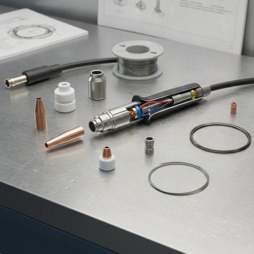
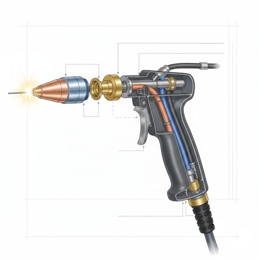
A MIG welder is made up of several core parts: the welding gun (torch), wire feed mechanism, contact tip, nozzle, liner, drive rolls, shielding gas system, and the power source. Each component plays a direct role in arc stability, wire delivery, and weld quality. If any single part is worn, misaligned, or incorrect for the material, the weld suffers.
The Welding Gun (MIG Torch)
The welding gun is what most people think of first, and it’s the part you actually hold. Inside the handle sits a trigger that activates the wire feed and gas flow simultaneously.
The gun connects to the welder through a cable assembly that carries welding current, shielding gas, and the wire electrode all at once. Most guns are rated by amperage — a 150A gun works fine for light hobby work, while production or heavy fabrication setups typically need 300A or higher.
Gun ergonomics matter more than people realize. A heavy, stiff gun causes fatigue, which leads to inconsistent travel speed and poor bead quality. Swanneck (goose-neck) style torches allow better access in tight corners compared to straight-body designs.
Contact Tip
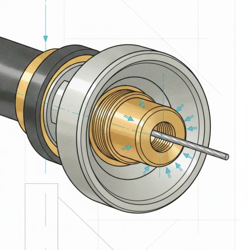
The contact tip is a small but critical copper component that sits at the end of the gun. The wire electrode passes through the contact tip, and that’s where electrical current transfers to the wire to create the arc.
Contact tips are sized to match wire diameter exactly:
– 0.023″ — for very thin wire, light sheet metal
– 0.030″ — common for mild steel work
– 0.035″ — standard for general fabrication
– 0.045″ — heavier wire for thicker base metal
Worn contact tips cause arc instability, wire sticking, and erratic feeding. In practice, a burned or oversized contact tip is one of the most common reasons for spatter and inconsistent welds. Most experienced welders keep a supply on hand and swap them routinely.
If you’re trying to understand what a quality MIG weld actually looks like, a fresh contact tip is often the first thing to check when your beads look rough.
Nozzle
The nozzle surrounds the contact tip and directs shielding gas over the weld puddle. It’s typically made from copper or brass for heat resistance.
Two main nozzle types exist:
Nozzle Type
Shape
Best Use
Cylindrical (straight)
Uniform bore
Flat and horizontal welding
Tapered (conical)
Narrower at tip
Tight spaces, corners, vertical welding
Spatter buildup inside the nozzle is a constant issue. Clogged nozzles restrict gas flow, leading to porosity in the weld. Nozzle dip compounds — or even a light coat of anti-spatter spray — reduce buildup and extend service life.
Nozzle standoff distance matters too. Holding the nozzle too far from the work surface lets atmosphere contaminate the shielding zone. Too close, and spatter quickly clogs the opening.
Wire Feed Mechanism and Drive Rolls
The wire feed system is the engine of consistent MIG welding. It pulls wire from the spool and pushes it through the liner and gun at a controlled, adjustable speed — measured in inches per minute (IPM).
Drive rolls grip the wire and feed it forward. They come in two configurations:
– V-groove rolls — for solid steel wire
– U-groove rolls — for soft aluminum wire (prevents deformation)
– Knurled rolls — for flux-cored wire, where extra grip is needed
Drive roll tension is easy to overlook. Too much pressure crushes soft wire and creates fine metal shavings that clog the liner. Too little tension causes slipping and inconsistent feed. A quick test: the wire should stop feeding if you hold it lightly with your fingers, but feed smoothly without that resistance.
Most mid-range to professional machines use a 4-roll drive system rather than 2-roll, which provides more consistent feed pressure — especially on longer gun cable assemblies.
Liner
The liner runs through the entire length of the gun cable and guides the wire from the drive rolls to the contact tip. It’s usually made from steel coil (for solid wire) or PTFE (Teflon) for aluminum wire.
A contaminated or kinked liner is one of the most overlooked causes of feeding problems. Wire that stutters, birdnests at the drive rolls, or produces an irregular arc often traces back to a liner that’s clogged with wire debris or worn out.
Liner replacement is straightforward on most guns but is frequently skipped until problems become severe. In a production environment, liners typically get replaced every few months depending on usage.
Shielding Gas System
Shielding gas protects the molten weld pool from atmospheric contamination — oxygen and nitrogen cause porosity and weaken the weld if they reach the arc zone.
The gas system includes:
– Cylinder — stores compressed gas
– Regulator/flowmeter — controls and measures gas flow (typically 15–25 CFH for most applications)
– Hose — connects regulator to the welder
– Solenoid valve — opens gas flow when the trigger is pulled
– Nozzle — directs gas at the weld pool
Gas selection depends on the base material. For mild steel, a 75/25 argon-CO₂ mix (C25) is the most widely used blend. Pure CO₂ runs hotter and produces more spatter but costs less. Aluminum requires 100% argon.
If you’re unsure whether your application actually requires shielding gas, it’s worth understanding when flux-cored wire serves as an alternative approach.
Wire Electrode (MIG Wire)
The wire electrode serves as both the filler metal and the conductor that carries the arc. It feeds continuously during welding, which is what separates MIG from stick welding.
Common wire types and their applications:
Wire Type
Common Diameter
Typical Use
ER70S-6 (solid mild steel)
0.030"–0.035"
General fabrication, auto body
ER308L (stainless)
0.030"–0.035"
Stainless steel welding
ER4043 / ER5356 (aluminum)
0.035"–0.047"
Aluminum welding
E71T-11 (flux-cored)
0.030"–0.045"
Outdoor, no-gas welding
Wire selection has to match the base metal. Using the wrong filler wire affects mechanical strength, corrosion resistance, and bead appearance. For example, welding stainless steel with standard mild steel wire creates a weld that looks acceptable but lacks the corrosion resistance the application requires.
Power Source
The power source (welder body) converts incoming electrical power into the controlled DC current used for welding. MIG welders use constant voltage (CV) output, which maintains arc length automatically as wire feed speed varies slightly.
Key settings on the power source:
– Voltage — controls arc heat and bead profile
– Wire feed speed (WFS) — determines amperage indirectly; faster feed = more amperage
– Inductance (on some machines) — controls arc smoothness and spatter
Transformer-based machines are heavier but handle duty cycle demands well. Inverter-based machines are lighter, more portable, and often more energy-efficient. The Lincoln Electric Weld-Pak 140 HD is a commonly referenced example of a reliable transformer-based unit for shop and home use, while inverter machines like the YESWELDER MIG-205DS offer multi-process capability in a more compact form.
Spool and Wire Feed Tension Brake
The wire spool sits on a hub inside the machine and unwinds as the wire feeds forward. A tension brake on the hub prevents the spool from overrunning — if this is set too loose, the spool free-spools and creates tangles. Too tight, and the drive rolls struggle to pull wire smoothly.
Most machines use a knurled knob or spring-loaded mechanism to adjust brake tension. The correct setting lets the spool stop immediately when wire feed stops, with no coasting or backlash.
Consumables Worth Tracking
Several MIG weld parts are consumables — they wear out and need regular replacement:
– Contact tips — replace when the bore is oval, burned, or causing arc issues
– Nozzles — replace when spatter buildup can’t be cleaned, or the bore is restricted
– Liner — replace when feeding becomes inconsistent despite correct drive roll tension
– Drive rolls — replace when grooves are worn smooth or edges have mushroomed
Keeping a small stock of these parts prevents unnecessary downtime. Many welders learn the hard way that a bad contact tip halfway through a project means either stopping to get supplies or pushing through with poor results.
FAQ
What is the most commonly replaced part on a MIG welder?
The contact tip is the most frequently replaced MIG weld consumable. It’s the smallest part under the most thermal stress, and it wears out faster than any other component. Most welders replace contact tips every few hours of active welding, depending on wire size, amperage, and material.
What does the MIG gun liner do and when should it be replaced?
The liner guides the wire electrode from the drive rolls through the cable to the contact tip. Over time, it accumulates wire debris, develops wear grooves, or gets kinked. Replace it when wire feeding becomes erratic, birdnesting occurs at the drive rolls, or cleaning the liner no longer resolves feeding issues. Most liners last several months with moderate use.
Why does my MIG welder have so much spatter, and which part is usually the cause?
Excessive spatter typically points to a worn contact tip, incorrect voltage settings, or a clogged nozzle restricting gas flow. It can also result from dirty base metal, incorrect wire stick-out distance, or using pure CO₂ shielding gas instead of a 75/25 argon-CO₂ blend. Start by checking the contact tip and nozzle before adjusting machine settings.
What are drive rolls and do they need to be matched to wire type?
Drive rolls are the grooved wheels that grip and feed the wire electrode. Yes, they must match the wire type — V-groove for solid wire, U-groove for aluminum, and knurled for flux-cored. Using the wrong profile either damages the wire or fails to grip it consistently, both of which cause feeding problems and arc instability.
Can I use the same MIG gun nozzle for all materials?
Generally yes, as long as the nozzle size matches your application. However, aluminum welding benefits from a slightly larger bore to maintain adequate gas coverage, since aluminum wire is softer and the gas envelope needs to be generous. Switching between mild steel and stainless is usually fine without changing nozzles, but clean the nozzle thoroughly between materials.
What does the solenoid valve do in a MIG welder?
The solenoid valve is an electrically controlled valve that opens gas flow the instant you pull the trigger and closes it when you release. It’s built into the welder body. If gas flow is inconsistent or doesn’t stop after releasing the trigger, a failing solenoid is usually the cause. It’s replaceable but less commonly serviced than external consumables.
How does wire feed speed affect the weld?
Wire feed speed directly controls the deposition rate and amperage. Increasing WFS feeds more wire into the puddle, which raises heat input and amperage. Too slow, and the arc becomes unstable and the weld undercuts. Too fast, and the wire pushes into the puddle rather than melting cleanly, causing stubbing, spatter, and rough beads. WFS must be balanced with voltage for each wire diameter and material thickness.
Every MIG weld part has a specific job, and most weld problems trace back to a worn, mismatched, or incorrectly set component rather than operator error alone. Knowing your equipment — from the drive rolls to the nozzle — lets you diagnose issues faster and maintain consistent weld quality without guesswork.