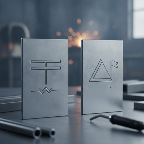
Reading a welding drawing without understanding the symbols is like reading a map in a foreign language. Two of the most commonly encountered symbols are the butt weld and fillet weld symbols — and confusing them can send a fabricator in completely the wrong direction.
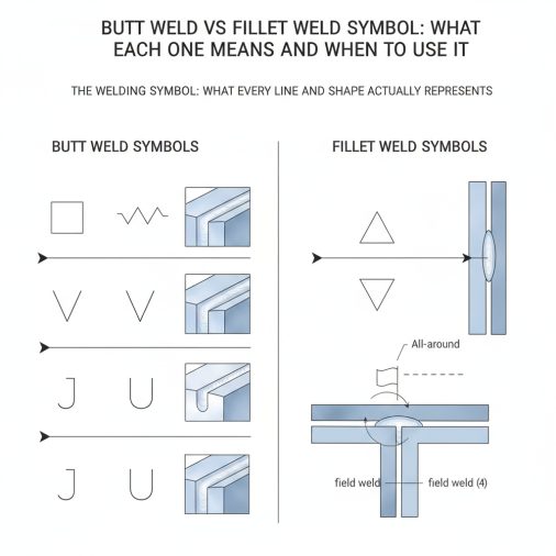
A fillet weld symbol uses a right triangle placed on the reference line to indicate a triangular cross-section weld joining two surfaces at an angle, typically 90°. A butt weld (groove weld) symbol uses specific geometric shapes — such as a square, V, bevel, U, or J — to indicate a weld made between two pieces aligned edge to edge in the same plane. The symbol used depends on the joint type, not the welding process.
The Welding Symbol: What Every Line and Shape Actually Represents
Before comparing the two symbols, it helps to understand how a welding symbol is built. Every welding symbol sits on an arrow line and a reference line (a horizontal baseline). A tail at the opposite end of the arrow may contain a welding process abbreviation or specification note.
The weld symbol itself — the small geometric shape — sits either below or above the reference line:
– Below the reference line = weld on the arrow side (the side the arrow physically points to)
– Above the reference line = weld on the other side
– Both sides = weld on both sides of the joint
This positioning applies to both butt and fillet weld symbols. Understanding it eliminates a huge amount of confusion when reading fabrication drawings.
The Fillet Weld Symbol Explained
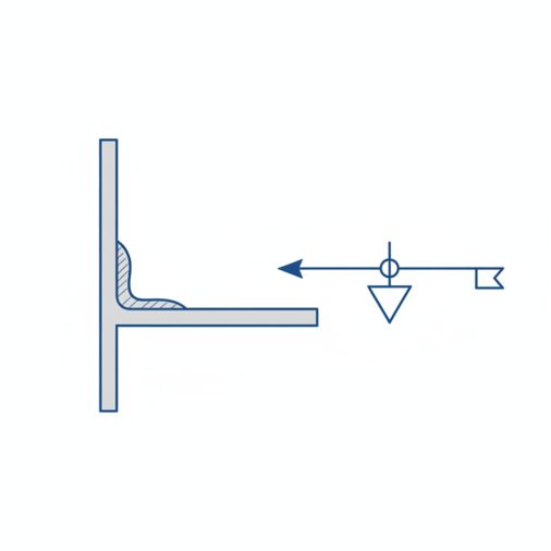
The fillet weld symbol is a small right triangle. It looks like the letter “L” with a diagonal line connecting the two legs — essentially a simplified cross-section of the weld itself.
Where it’s placed:
– Below the reference line → weld on the arrow side
– Above the reference line → weld on the other side
– Both positions → weld on both sides (common for T-joints)
What the numbers mean:
– A number to the left of the triangle = weld size (leg length)
– A number to the right = weld length
– Numbers in parentheses indicate intermittent weld spacing
For example, a symbol showing 3/8 to the left means a 3/8″ fillet weld. If a dash and number follow, such as 3/8 – 2 – 5, that indicates 3/8″ leg size, 2″ weld length, and 5″ center-to-center spacing.
Fillet welds are most often used on:
– T-joints
– Lap joints
– Corner joints
They don’t require edge preparation, which makes them faster and more economical for many structural applications. Knowing practical fillet weld sizing rules helps ensure the specified size on the symbol actually meets load requirements.
The Butt Weld Symbol Explained
Butt weld symbols — more precisely called groove weld symbols in AWS terminology — represent welds made between two pieces positioned end-to-end in the same plane. The specific symbol shape tells the welder what groove preparation is required.
Groove Type
Symbol Shape
Typical Use
Square groove
Two parallel vertical lines
Thin material, low-stress joints
V-groove
Two angled lines forming a V
Full penetration on medium/thick plate
Bevel groove
One vertical, one angled line
Single-sided joint prep
U-groove
Curved U shape
Thick plate, reduces filler volume
J-groove
Single curved shape
One-sided, heavy sections
Flare-V groove
Two curved lines
Formed or tubular sections
The V-groove symbol is by far the most common butt weld symbol in structural and pressure vessel work. When you see it, the joint requires the base metal edges to be cut or ground to form a V-shape before welding.
Key modifiers on groove weld symbols:
– Root opening = number inside the symbol
– Groove angle = number outside the symbol (e.g., 60°)
– Depth of preparation = number in parentheses to the left
– Weld size = number outside parentheses to the left
– Contour symbols (flush, convex, concave) appear on or above the symbol
A filled circle at the arrow line junction indicates an all-around weld. A flag at the reference line tail indicates a field weld.
Understanding how butt welding works mechanically helps make these symbol details more intuitive when you see them on a drawing.
Key Differences at a Glance
Feature
Fillet Weld Symbol
Butt (Groove) Weld Symbol
Symbol shape
Right triangle
V, square, bevel, U, J, etc.
Joint type
T-joint, lap, corner
Butt joint (edge-to-edge)
Edge prep required
Usually none
Often required (beveling, grinding)
Penetration type
Partial (typically)
Full or partial depending on type
Size notation
Leg length to the left
Effective throat or depth to the left
Common application
Structural attachments, brackets
Pipe joints, pressure vessels, structural splices
The most important practical difference: fillet welds are placed at an intersection of two surfaces, while groove welds are placed between two edges prepared to receive the weld.
How to Read Combined Weld Symbols
In real fabrication drawings, you’ll sometimes see both symbol types used together or in sequence across a joint. A weld procedure for a corner joint, for example, might specify a bevel groove on the inside and a fillet weld reinforcement on the outside.
When both appear on the same reference line:
– Each symbol occupies its own side (above or below)
– Each side may have different dimensions
Always read the arrow-side symbol and the other-side symbol independently. Swapping them is a common mistake that leads to welding the wrong side or applying the wrong joint prep.
Common Mistakes When Interpreting These Symbols
Misreading arrow-side vs. other-side placement is the most frequent error in shop settings. Welders sometimes apply the fillet to the opposite side from what the drawing specifies, which affects load path and may violate the engineering intent.
Confusing weld size with throat thickness trips up less experienced fabricators. For fillet welds, the size refers to the leg, not the effective throat. The effective throat of a standard fillet weld is approximately 0.707 × leg size — an important distinction when calculating joint strength. You can explore this further by looking at how to calculate welded joint strength.
Ignoring groove angle specifications on butt weld symbols can result in inadequate joint penetration or excessive filler metal use. Both have consequences — one structural, one economic.
Skipping the tail information is another overlooked detail. The tail may reference a specific welding procedure specification (WPS) that dictates process, consumable, and preheat requirements.
Field experience shows that even experienced welders occasionally misread intermittent fillet weld callouts, mistaking total weld length for segment length. A symbol reading ¼ – 2 – 6 means quarter-inch fillet welds, each 2 inches long, spaced 6 inches apart center-to-center — not a continuous 2-inch weld every 6 inches from the end.
AWS vs. ISO Symbol Differences
Most North American drawings follow AWS A2.4, the standard for welding symbols. European and international drawings typically follow ISO 2553, which uses a different placement logic.
In ISO 2553:
– The arrow points directly to the joint
– The symbol sits below the reference line for the arrow-side weld (same as AWS)
– A dashed line below the reference line indicates the other side — this dashed line is absent in AWS
If you’re reading a drawing from a European supplier or working on an international project, verify which standard applies before interpreting any symbol. The shapes look similar, but the placement rules differ enough to cause errors.
Practical Tips for Applying Symbols Correctly
– Always identify the joint type first. The joint geometry tells you whether a fillet or groove symbol is even applicable.
– Check both sides of the reference line before starting. Many joints are double-sided.
– Look for supplementary symbols — backweld, backing bar, melt-through — that appear near the groove symbol and affect how you set up the joint.
– Verify weld size against material thickness. AWS D1.1 and similar codes specify minimum fillet weld sizes based on base metal thickness, and drawings don’t always repeat those requirements.
– Use a weld gauge after welding. Symbols specify intent; gauges confirm results. Measuring fillet weld size properly is a skill worth developing early.
FAQ
What does the triangle in a fillet weld symbol represent?
The right triangle in a fillet weld symbol is a simplified cross-section of the actual weld bead. The vertical leg represents the fusion face on the upright member, and the horizontal leg represents the base surface. The number to the left of the triangle indicates the weld leg size, which determines how large the weld cross-section should be.
Can a fillet weld symbol appear on the same drawing as a groove weld symbol?
Yes, and it’s common. A joint might require a groove weld on one side for full penetration and a fillet weld on the other side as a reinforcing pass. Each symbol appears on its respective side of the reference line. Reading them independently — with their own size callouts and locations — prevents confusion during fabrication.
What does the number next to a butt weld symbol mean?
For groove weld symbols, a number to the left in parentheses indicates the depth of groove preparation, while the number outside the parentheses indicates the effective weld size (throat depth). A groove angle appears as a degree value within or beside the symbol geometry. Root opening is typically shown as a number inside the symbol itself.
How do I know if a butt weld needs full or partial penetration?
Full joint penetration (FJP) is typically specified by a note in the tail of the welding symbol or indicated on the drawing’s general notes. Without a specific FJP callout, a groove weld may be interpreted as partial joint penetration (PJP). In critical structural and pressure applications, always confirm penetration requirements with the engineer or the applicable code document.
What is the difference between a weld symbol and a welding symbol?
This is a distinction AWS A2.4 specifically makes. The weld symbol is just the geometric shape (triangle, V, etc.) indicating the weld type. The welding symbol is the complete assembly — including the reference line, arrow, weld symbol, dimensions, supplementary symbols, and tail. The full welding symbol communicates everything a welder and inspector need to know about a specific weld.
Why does the fillet weld triangle sometimes point in different directions?
The orientation of the fillet weld triangle indicates whether the weld is on the arrow side or other side, but the triangle shape itself remains consistent. Some drafting software or older drawings may rotate the symbol slightly, but the key indicator is always which side of the reference line the symbol sits on — not the rotational orientation of the triangle.
Can both fillet and groove welds develop weld defects from misread symbols?
Absolutely. Misreading a symbol can lead to undersized welds, incorrect joint preparation, or welds placed on the wrong side of a joint. All of these can contribute to structural failures. Understanding common weld defect types helps connect symbol errors to their real-world consequences during inspection.
The fillet weld symbol and butt (groove) weld symbol look nothing alike — a triangle versus a V, square, or bevel shape — and that difference is intentional. Each symbol encodes not just the weld type but the joint geometry, edge preparation, and positional intent. Getting comfortable with both symbols, and learning to read all the dimensional callouts attached to them, is one of the most practical skills anyone working from fabrication drawings can develop.