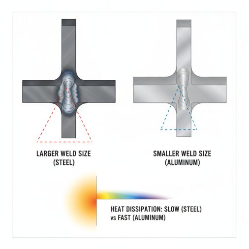
Sizing a weld on aluminum isn’t the same as sizing one on steel. Aluminum conducts heat faster, has lower tensile strength per alloy grade, and responds differently to heat input — which means weld size decisions that work fine on mild steel can leave an aluminum joint under-built or thermally distorted.
Aluminum fillet weld sizes typically follow the same minimum-size rules as steel under AWS D1.2 (the Structural Welding Code for Aluminum), but the calculations must account for aluminum’s lower base metal strength. For most structural aluminum joints, minimum fillet weld leg size ranges from 3/16″ (4.8 mm) for thinner material up to 5/16″ (8.0 mm) for thicker plate. The throat size — not the leg — is what actually determines load-carrying capacity, and effective throat for a fillet weld equals approximately 0.707 × leg size.
Why Aluminum Weld Sizing Differs From Steel
Steel welding codes, particularly AWS D1.1, are what most welders learn first. When you move to aluminum, AWS D1.2 governs — and a few things shift.
Aluminum alloys vary significantly in strength. A 6061-T6 joint has a different allowable shear stress than a 5052-H32 joint. Filler wire selection also affects the final joint strength, so the weld size chart you use must align with your base metal and filler combination.
Heat input matters more, too. Because aluminum absorbs and dissipates heat rapidly, achieving full fusion at the root of a small fillet is harder. Undersized welds on aluminum are more likely to be cold or lack proper tie-in than on steel. If you’re selecting your filler wire, the TIG welding filler rod selection chart covers alloy-specific filler recommendations that directly affect joint design strength.
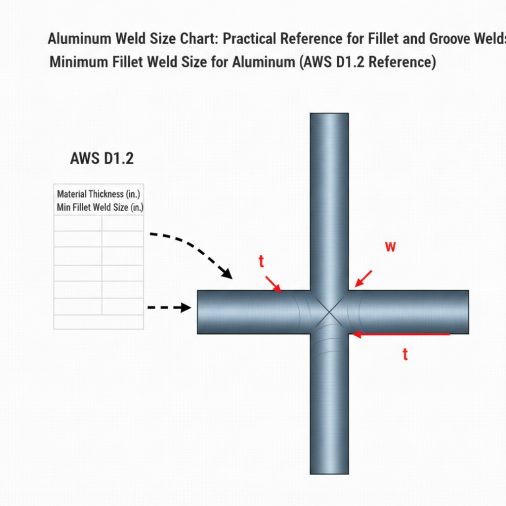
Minimum Fillet Weld Size for Aluminum (AWS D1.2 Reference)
The table below reflects the general minimum fillet weld leg sizes for aluminum structural applications. These are based on the thinner part being joined.
Base Metal Thickness (Thinner Part)
Minimum Fillet Weld Leg Size
Up to 1/4" (6.4 mm)
1/8" (3.2 mm)
Over 1/4" to 1/2" (6.4–12.7 mm)
3/16" (4.8 mm)
Over 1/2" to 3/4" (12.7–19 mm)
1/4" (6.4 mm)
Over 3/4" to 1-1/2" (19–38 mm)
5/16" (8.0 mm)
Over 1-1/2" (38 mm+)
3/8" (9.5 mm)
These are minimums. Structural engineers frequently specify larger sizes based on load calculations and joint efficiency factors. Always verify against your project drawings.
Maximum Fillet Weld Size for Aluminum
Maximum weld size is just as important as minimum size. Oversized welds waste filler material, introduce excess heat, and can cause distortion in aluminum — which warps much more readily than steel under thermal load.
For plates and flat bar, the standard rule is:
– Material ≤ 1/4″ thick: Maximum fillet weld leg = full material thickness
– Material > 1/4″ thick: Maximum fillet weld leg = material thickness minus 1/16″
For example, on 3/8″ aluminum plate, the maximum fillet weld leg size is 3/8″ − 1/16″ = 5/16″. Depositing a 3/8″ fillet on that same plate adds no structural value and significantly increases heat input. The maximum fillet weld size for plate thickness follows the same principles whether you’re working with aluminum or steel.
Throat Size and Actual Weld Strength
Leg size is what you measure with a gauge. Throat size is what determines how much load the weld can actually carry.
For a standard 45° fillet weld:
> Effective throat = 0.707 × leg size
So a 1/4″ (6.4 mm) fillet weld has an effective throat of approximately 0.177″ (4.5 mm).
Allowable shear stress on the weld throat for aluminum depends on filler wire classification. Common values under AWS D1.2 for typical filler alloys:
Filler Wire
Minimum Tensile Strength (As-Welded)
Allowable Shear on Throat
ER4043
27,000 psi (186 MPa)
~11,700 psi
ER5356
35,000 psi (241 MPa)
~15,000 psi
ER4047
24,000 psi (165 MPa)
~10,400 psi
ER5356 is the stronger filler for structural applications. ER4043 flows more easily and is better suited for thin or heat-sensitive alloys. Knowing this distinction matters when sizing a weld for a specific load requirement.
Aluminum Fillet Weld Size for Common Structural Applications
For fabricators who need quick reference values, this table covers typical application scenarios rather than abstract thicknesses.
Application
Typical Material Thickness
Recommended Fillet Weld Size
Aluminum extrusion frame joints
1/8"–3/16"
1/8"–3/16"
Marine deck grating support
3/16"–1/4"
3/16"
Structural aluminum bracket
1/4"–3/8"
1/4"–5/16"
Aluminum trailer frame rail
3/8"–1/2"
5/16"–3/8"
Heavy structural column base
1/2"+
3/8"–1/2"
These values assume single-pass fillet welds with full fusion. Multi-pass welds are typically required when leg size exceeds 5/16″ to maintain heat control and avoid porosity.
How to Determine the Right Weld Size for Your Job
Using a chart is the starting point, not the endpoint. Proper weld sizing follows a logical sequence:
1. Identify the thinner material — minimum size is governed by the thinner base metal, not the thicker one
2. Check your code — AWS D1.2 for structural aluminum; ASME or military specs if applicable
3. Determine load requirements — static, dynamic, or fatigue loading affects allowable stresses
4. Select filler wire — ER5356 for strength, ER4043 for ease of welding on 6061
5. Calculate throat using the load — back-calculate required leg size from throat requirement
6. Apply maximum size limit — don’t exceed plate thickness minus 1/16″ unless noted on drawing
For a deeper look at the calculation process, the guide on how to determine proper weld size walks through the load-based approach with practical examples.
Measuring Aluminum Fillet Welds in the Field
Fillet weld gauges work the same way on aluminum as on steel. The most common type is a bridge cam gauge or a set of fillet weld gauges that measure leg size directly.
A common mistake is measuring convex or concave welds as if they were perfect 45° triangles. A concave fillet weld may appear to have the right leg size but have a reduced throat — which is what actually carries the load. Measuring throat directly requires a different gauge orientation.
If you’re not familiar with the gauging process, how to measure a fillet weld size covers the step-by-step technique including common measuring mistakes to avoid.
MIG vs. TIG Weld Sizing Considerations for Aluminum
The welding process affects how a weld is sized and specified in practice.
MIG (GMAW) on aluminum typically uses a spool gun or push-pull setup to handle soft aluminum wire. Higher travel speeds and wire feed rates mean you can deposit material quickly, but controlling leg size on thin material requires experience. The aluminum MIG welding wire speed and voltage chart provides process settings by material thickness.
TIG (GTAW) on aluminum gives much tighter control over heat input and weld puddle size, making it the preferred process for precision-sized welds in aerospace, marine, and custom fabrication work. TIG welds are easier to hold to a specified leg size consistently.
For most structural applications using 1/4″ plate and above, MIG is practical and fast. For thinner material — say, 1/8″ and under — TIG gives better control and less distortion.
The Lincoln Electric Viking 3350 auto-darkening helmet is worth mentioning here: the wide shade range (5–13) handles both the bright arc of aluminum MIG and the lower-intensity TIG arc, which is genuinely useful when switching processes on the same project.
Common Mistakes When Sizing Aluminum Welds
Field experience consistently shows the same errors coming up on aluminum work:
– Applying steel minimum sizes without checking D1.2 — they’re often similar but not always identical
– Ignoring the effect of filler wire on strength — using ER4043 where ER5356 was needed undercuts joint capacity
– Oversizing to compensate for uncertainty — more weld means more heat, more distortion, and no real safety gain
– Skipping throat verification on concave welds — a weld that visually looks adequate may be short on effective throat
– Single-passing welds that need multiple passes — beyond 5/16″ leg size, multiple passes maintain quality and minimize defects
A practical checkpoint: if your weld is showing porosity, cold lap, or inconsistent fusion, the issue is often process-related rather than a size issue. Tighten up your travel speed, torch angle, and gas coverage before simply adding more weld material.
FAQ
What is the minimum fillet weld size for 1/4″ aluminum plate?
For 1/4″ aluminum plate, the minimum fillet weld leg size under AWS D1.2 is 1/8″ (3.2 mm) if the thinner part is at or under 1/4″. If the joint includes material thicker than 1/4″, the minimum bumps up to 3/16″. Always check the applicable code and drawing notes for your project, since engineers often specify larger sizes based on load requirements beyond the code minimum.
How do I calculate the required weld size for an aluminum fillet weld under load?
Start by determining the allowable shear stress on the weld throat for your filler wire (e.g., ~15,000 psi for ER5356). Divide the applied shear force per inch of weld by that value to get the required throat size. Then divide throat by 0.707 to get the required leg size. Round up to the nearest standard size, and check it against both minimum and maximum limits for the base metal thickness.
Is AWS D1.2 the right code for all aluminum welding?
AWS D1.2 governs structural aluminum welding for buildings, bridges, and general fabrication. However, aerospace applications often follow AWS D17.1, pressure vessels may follow ASME Section IX, and military or government contracts may reference MIL-STD specifications. Always verify which code applies before designing a joint or specifying weld sizes.
Does weld position affect the required size for aluminum?
Yes, in practice. Overhead and vertical welds are harder to control on aluminum because the molten puddle is very fluid. A weld sized at 3/16″ in the flat position may require a multi-pass approach overhead to achieve the same effective throat without sagging or lack of fusion. Code-minimum sizes stay the same, but process parameters and technique must be adjusted for position.
Can I use a steel fillet weld chart for aluminum?
Not reliably. Steel and aluminum have different base metal strengths, allowable stresses, and code requirements. Using a steel chart for aluminum may result in undersized welds (if the chart was based on higher steel strength) or unnecessarily oversized welds. AWS D1.2 is the correct reference for aluminum structural welds, and it should always be consulted alongside your filler wire data.
What filler wire gives the strongest aluminum fillet weld?
ER5356 consistently produces higher tensile and shear strength than ER4043 in aluminum fillet welds. Its minimum tensile strength as-welded is typically around 35,000 psi, compared to 27,000 psi for ER4043. For structural joints where load capacity drives weld size, ER5356 is the standard choice. ER4043 is better suited to crack-sensitive alloys like 6061 where fluidity and cosmetics matter more than raw strength.
What’s the effective throat of a 3/8″ aluminum fillet weld?
The effective throat equals 0.707 × leg size. For a 3/8″ (9.5 mm) fillet weld, the effective throat is approximately 0.265″ (6.7 mm). This is the measurement used to calculate load-carrying capacity — not the leg size itself. If the weld profile is concave, actual throat may be slightly less than the theoretical value, which is why minimum fillet weld size requirements also account for weld profile in quality control.
Getting Weld Sizing Right the First Time
Aluminum weld sizing comes down to three things working together: knowing the applicable code, selecting the right filler wire, and understanding that effective throat — not visual leg size — is what actually carries the load. Use the charts here as a reference, but always verify against your project specifications and applicable welding code before finalizing any joint design. When in doubt, work with a certified welding inspector or structural engineer, especially on load-bearing assemblies where undersized welds create real safety risk.