If you’ve ever looked at a fabrication drawing and seen strange arrows, lines, and numbers clustered together, you were looking at weld symbols. They’re not random — they’re a precise language that tells welders exactly where to weld, what type of joint to use, and how large the weld should be.
Weld symbols are standardized graphical notations placed on engineering and fabrication drawings to communicate welding requirements. Each symbol indicates the weld type (such as fillet, groove, or plug), its location relative to the joint, size, length, and any special finishing instructions — all without written notes cluttering the drawing.
The Anatomy of a Weld Symbol
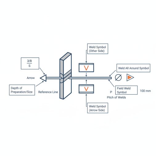
Every weld symbol is built from the same basic framework. Once you understand the components, any symbol becomes readable.
The framework includes:
– Reference line — A horizontal dashed or solid line that anchors the symbol
– Arrow — Points from the reference line to the joint being welded
– Weld symbol (basic) — Placed above or below the reference line to indicate weld type
– Dimensions — Numbers placed to the left (size) and right (length) of the basic symbol
– Tail — An optional forked end on the reference line used for notes or process specifications
– Supplementary symbols — Additional instructions such as “weld all around” or “field weld”
The arrow side of the reference line refers to the near side of the joint. Symbols placed above the reference line refer to the other side of the joint. This is one of the most commonly misread elements in fabrication drawings.
Basic Weld Symbol Types
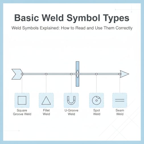
There are several core weld symbols you’ll encounter on almost every drawing. Each represents a different weld geometry.
Symbol Name
Appearance on Drawing
Common Use
Fillet weld
Right triangle
Joining two surfaces at an angle (T-joints, lap joints)
Square groove
Two vertical lines
Butt joints on thin material
V-groove
Chevron shape
Full-penetration butt joints
Bevel groove
Half-chevron
One-sided joint preparation
J-groove
Curved bevel shape
Heavy plate, reduced prep volume
U-groove
Curved double-bevel
Thick plate requiring full penetration
Plug or slot weld
Circle or rectangle
Joining overlapping plates through a hole
Spot weld
Circle with X or dots
Resistance welding, thin sheet
Seam weld
Ellipse
Continuous resistance weld
Back or backing weld
Curved line (opposite side)
Root reinforcement on groove welds
Surfacing weld
Straight line with buildup
Adding material to a surface for wear or restoration
Fillet welds are by far the most common symbol seen in structural and manufacturing drawings. They’re used wherever two plates meet at roughly 90 degrees.
How to Read the Numbers on a Weld Symbol
The numbers surrounding the basic weld symbol carry all the sizing information a welder needs.
For a fillet weld:
– The number to the left of the symbol = leg size (e.g., 5/16 or 8mm)
– The number to the right = weld length
– A dash followed by another number on the right = pitch (center-to-center spacing for intermittent welds)
For groove welds:
– The number in parentheses = root opening
– The angle shown = included groove angle (e.g., 60°)
– A depth number before the symbol = depth of bevel or effective throat
For example, a symbol showing `1/4 (3/16)` on a V-groove means a 3/16″ root opening with a 1/4″ effective throat. These details directly influence joint preparation and weld quality — misreading them is a common source of costly rework.
Supplementary Symbols and What They Mean
Beyond the basic weld type, several additional symbols modify or extend the instruction.
Weld-all-around — A small circle where the arrow meets the reference line. Means the weld continues completely around the joint with no gaps.
Field weld — A filled (solid) flag at the tail of the arrow. Indicates the weld is performed on-site, not in the shop. This matters for inspection and procedure planning.
Melt-through — A circle filled with a dot, placed opposite the basic symbol. Used when complete joint penetration must be visible on the back side.
Contour symbols — Flat, convex, or concave finish shapes placed on top of the basic symbol. Combined with a finishing letter (G for grinding, C for chipping, M for machining), they specify how the weld face should look after completion.
Backing bar — A rectangle placed on the opposite-side symbol, sometimes with an R inside to indicate a removable backing strip.
These supplementary symbols are where many beginners struggle, largely because they’re rarely explained alongside the basic symbol types.
AWS vs. ISO Weld Symbols
Weld symbols aren’t universal. Two major systems exist, and mixing them up creates real problems.
AWS A2.4 (American Welding Society) is the standard used in the United States and much of North America. It places the basic weld symbol above or below the reference line based on arrow side / other side.
ISO 2553 is used throughout Europe, Australia, and much of Asia. It uses a similar reference line but positions symbols differently — the dashed line is placed below the reference line to indicate the far side, opposite to the AWS convention.
Feature
AWS A2.4
ISO 2553
Arrow side symbol
Below reference line
Above reference line
Other side symbol
Above reference line
Below reference line (dashed line)
Groove angle placement
Inside symbol
Alongside symbol
Common regions
North America
Europe, Asia-Pacific
If you’re working with drawings from overseas fabricators, confirming which standard applies before cutting or prepping material is worth the extra minute it takes.
Common Mistakes When Reading Weld Symbols
Even experienced welders misread symbols under production pressure. The most frequent issues include:
– Ignoring arrow side vs. other side — Welding on the wrong face of a joint is more common than most shops like to admit
– Misreading intermittent weld pitch — Confusing weld length for pitch spacing creates undersized connections
– Skipping the tail — Process specifications or procedure numbers written in the tail are sometimes missed entirely
– Assuming symmetry — Not all symbols are mirrored on both sides; always check each side independently
– Confusing effective throat with leg size — On fillet welds, the effective throat is approximately 0.707 times the leg size, which matters for calculating weld strength
In practice, keeping a weld symbol reference chart at the workstation significantly reduces these errors, especially when handling complex multi-pass or combination joint symbols.
Practical Tips for Working With Weld Symbols in the Field
Reading symbols on a clean drawing at a desk is one thing. Interpreting them accurately on a busy shop floor or a cramped field job is another.
– Always orient the drawing the same way as the actual part when reading symbols
– Mark arrow-side welds with a paint marker before flipping the part
– When a symbol is unclear, consult the engineer or detailer before welding — never guess on structural connections
– Use AWS D1.1 (Structural Welding Code — Steel) as a reference alongside drawing symbols for structural work
– For multi-process jobs, the tail of the symbol often references a Welding Procedure Specification (WPS) number — pulling that document gives you parameters, not just geometry
Understanding what a good weld looks like once you’ve completed it is equally important. If you’re learning to assess your own work, knowing what a quality MIG weld appearance looks like helps confirm you’ve met the symbol’s intent.
FAQ
What is the difference between a weld symbol and a welding symbol?
A welding symbol refers to the complete notation on a drawing, including the reference line, arrow, dimensions, supplementary symbols, and tail. A weld symbol specifically refers to the basic geometric shape (such as a fillet or V-groove) placed on the reference line. The terms are often used interchangeably in conversation, but the technical distinction matters in engineering documentation.
What does a circle on a weld symbol mean?
A small open circle at the junction of the arrow and the reference line means “weld all around.” This tells the welder to continue the weld completely around the entire perimeter of the joint without stopping. It’s commonly used on pipe connections, structural posts, and bracket attachments where all-around sealing or strength is required.
How do I know which side of a joint to weld on?
The arrow points directly to the joint location. If the basic weld symbol appears below the reference line, the weld goes on the arrow side — the side the arrow physically touches. If the symbol appears above the reference line, the weld goes on the opposite side. When symbols appear both above and below, both sides receive welds.
What does the number to the left of a fillet weld symbol mean?
The number to the left of a fillet weld symbol indicates the leg size of the weld. For example, a 3/8 fillet weld has a 3/8″ leg. This dimension controls how much filler material is deposited and directly affects the load capacity of the connection. Always confirm units (inches or millimeters) based on the drawing’s title block.
What is an intermittent weld symbol?
An intermittent weld is indicated by two numbers to the right of the basic symbol, separated by a dash. The first number is the weld length, and the second is the pitch (center-to-center distance between welds). For example, `4-10` means 4″ welds spaced 10″ apart center-to-center. Intermittent welds are used where continuous welding would cause distortion or is structurally unnecessary.
Do weld symbols specify the welding process?
The basic symbol and dimensions don’t specify the process — those are typically referenced in the tail of the welding symbol, either as a letter abbreviation (GMAW, GTAW, SMAW) or as a WPS number. When no process is specified, the fabricator or contractor typically selects based on material, position, and applicable code.
Why do some weld symbols have a dashed reference line?
In ISO 2553, the dashed reference line is used to identify the far (other) side of the joint — the opposite convention from AWS. In AWS drawings, you may occasionally see a dashed extension added informally for clarity, but this is non-standard. If you encounter a dashed line, confirm whether the drawing uses AWS or ISO notation before proceeding.
Weld symbols are a precision communication tool. Getting them right means the fabricated part performs as the engineer intended — getting them wrong can result in structural failure, rework, and liability. Whether you’re reading your first drawing or reviewing complex multi-pass joint designs, treating each symbol as a complete instruction set — not just a shape on a line — is what separates reliable fabrication from guesswork.