
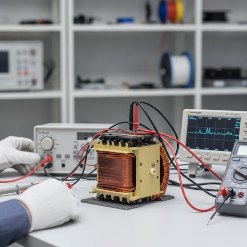
A faulty MIG transformer is one of the most misdiagnosed problems in welding equipment repair. Whether your machine produces weak arc output, no output at all, or overheats without explanation, the transformer is often the first component suspected — but not always the right one to replace. This article walks you through exactly how to test a MIG transformer using a multimeter, explains what the readings mean, and helps you distinguish a failed transformer from other common causes of MIG welder failure.
To test a MIG transformer, disconnect the machine from power, then use a multimeter set to resistance (ohms) mode. Measure continuity across the primary and secondary windings separately. A good winding shows low resistance (typically under 10 ohms); an open circuit reading (OL or infinite resistance) indicates a failed winding. Also check for shorts between windings and between windings and the core.
What a MIG Transformer Actually Does
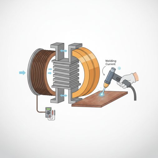
The transformer in a MIG welder converts high-voltage, low-current mains power into the low-voltage, high-current output needed for welding, so understanding make plasma cutter microwave 8211 can make the next step clearer. Most MIG transformers step down 120V or 240V AC input to somewhere between 17V and 45V on the secondary side, depending on the machine’s voltage settings.
Inside the transformer, two separate coils of wire — the primary winding and the secondary winding — are wound around a laminated iron core. The primary receives mains power; the secondary delivers welding voltage. These windings must remain electrically isolated from each other and from the core itself.
When a winding fails, it typically does so in one of three ways: an open circuit (broken wire), a short circuit (winding turns fused together), or an insulation breakdown causing a short to the core. Each failure mode produces different symptoms and different multimeter readings.
Tools and Safety Requirements Before You Start
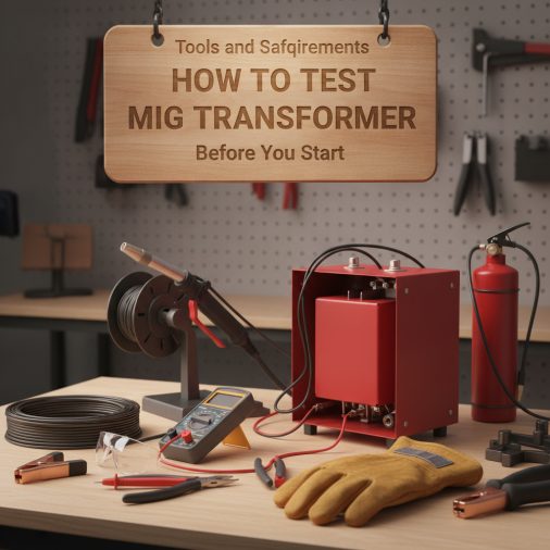
Tools needed:
– Digital multimeter (DMM) with continuity, resistance, and AC voltage modes
– Insulated screwdrivers for panel removal
– Electrical tape or marking tape for labeling wires
– Optional: clamp meter for live current measurement
Safety requirements — do not skip these:
– Unplug the MIG welder completely from the wall outlet before opening the case
– Wait at least 60 seconds after unplugging — capacitors in the circuit can hold residual charge
– Never test resistance or continuity on a live circuit; this will damage your multimeter and risks electrocution
– Work on a dry, non-conductive surface
– If the machine has a large capacitor bank (common in inverter-based MIG units), discharge it using a resistor before probing
MIG transformers in traditional (non-inverter) machines are large, heavy components with exposed terminals. Inverter-based MIG welders use smaller high-frequency transformers but require additional care due to the complex circuitry surrounding them.
How To Locate the Transformer Inside Your MIG Welder
Remove the outer casing by unscrewing the side or top panels. The transformer is typically the largest and heaviest component inside — a rectangular block of laminated steel with visible wire windings. It will have at least two sets of leads coming off it: the primary leads (connecting to the power input side) and the secondary leads (connecting to the rectifier or output terminals).
Take a photo before disconnecting anything. Label each wire with tape before removing it. On most machines, the primary winding leads are thinner wire (higher voltage, lower current), while the secondary leads are thicker wire or copper strap (lower voltage, higher current).
Disconnect the transformer leads from the circuit so you are testing the transformer in isolation, not the surrounding components.
Step-by-Step: Testing the MIG Transformer with a Multimeter
Step 1 — Test Primary Winding Resistance
Set your multimeter to resistance (Ω) mode. Place one probe on each of the two primary winding leads.
A healthy primary winding will show a low but measurable resistance — typically between 1 ohm and 10 ohms depending on the machine’s power rating. Larger, higher-amperage machines tend toward the lower end of this range.
| Reading | What It Means |
|---|---|
| 1–10 Ω | Normal — winding is intact |
| 0 Ω or near zero | Short circuit between winding turns |
| OL / infinite | Open circuit — broken winding wire |
Step 2 — Test Secondary Winding Resistance
Repeat the same test across the secondary winding leads. Secondary windings carry higher current and use heavier wire, so resistance values are typically even lower — often 0.1 to 2 ohms on the secondary side.
An open circuit reading here is a clear failure indicator. A reading of exactly zero ohms on a winding that should show some resistance suggests a dead short.
Step 3 — Check Insulation Between Primary and Secondary Windings
This test checks whether the two windings are accidentally making electrical contact with each other — a dangerous fault condition.
Set your multimeter to its highest resistance range (or use a dedicated insulation tester / megohmmeter if available). Place one probe on a primary lead and the other on a secondary lead.
Expected reading: OL (infinite resistance) — no continuity between windings.
Any measurable resistance here indicates insulation breakdown between the windings. This is a serious fault. The transformer should not be used.
Step 4 — Check for Shorts to the Core
Place one probe on any winding lead and the other probe directly on the transformer’s metal core (the laminated steel body). You should again see OL — no continuity.
A reading showing continuity between any winding and the core means the insulation has failed and the winding is grounding to the core. This creates a shock hazard and will cause erratic or zero output.
Step 5 — Verify AC Output Voltage (Live Test — Caution Required)
If resistance tests pass but you still suspect the transformer, a live voltage test confirms actual output. This step requires the machine to be powered — use extreme caution.
Reassemble the machine enough to safely power it. Set your multimeter to AC voltage mode. With the machine running at a known voltage setting, measure the AC voltage across the secondary winding output terminals before the rectifier.
Compare this reading to the machine’s rated secondary voltage (found in the service manual or on the data plate). A significant drop from rated voltage under no-load conditions suggests a partial winding fault that resistance testing alone may not catch.
Reading Your Results: What’s Failed and What Isn’t
| Test Result | Likely Fault | Action |
|---|---|---|
| Primary open circuit | Broken primary winding | Replace transformer |
| Secondary open circuit | Broken secondary winding | Replace transformer |
| Primary near-zero resistance | Shorted primary turns | Replace transformer |
| Continuity between windings | Insulation failure | Replace transformer — do not use |
| Continuity to core | Winding grounded to core | Replace transformer |
| All resistance tests pass | Transformer likely OK | Test rectifier, capacitors, and control board |
| Low AC output voltage | Partial winding fault or core saturation | Replace transformer |
When the Transformer Tests Fine But the Welder Still Fails
A transformer that passes all resistance and voltage tests is almost certainly not the problem. In practice, many MIG welder faults that appear to be transformer-related are actually caused by:
– Failed rectifier diodes — these convert AC to DC after the transformer; a shorted diode causes overheating and erratic output
– Faulty thermal overload switch — trips and cuts power before reaching the transformer
– Burned wire connections — loose or corroded terminals between the transformer and rectifier
– Capacitor failure — affects output smoothing in some designs
– Control board faults — especially in wire feed speed and voltage regulation circuits
Testing the transformer first is correct procedure, but always continue diagnostically through the full power path before ordering parts.
Common Mistakes When Testing MIG Transformers
Testing with power connected — resistance and continuity tests must be done with the machine unplugged. Testing live with a multimeter in resistance mode will give false readings and risks meter damage or injury.
Not isolating the transformer from the circuit — if the transformer leads are still connected to the rectifier or other components, your resistance readings will include those components and produce misleading results.
Expecting exact resistance values — resistance values vary between machines. What matters is whether the reading is reasonable (low but not zero) versus clearly open or shorted. Always cross-reference with your machine’s service documentation when available.
Confusing the primary and secondary leads — mixing these up during reassembly can cause immediate damage when power is restored. Label everything before disconnecting.
FAQ
Can I test a MIG transformer without removing it from the machine?
You can perform basic resistance tests without full removal, but you must disconnect the transformer leads from the surrounding circuit. Testing with leads still connected to the rectifier or other components will produce inaccurate readings. At minimum, disconnect all four leads (two primary, two secondary) before measuring resistance values.
What resistance should a MIG welder transformer show?
Primary winding resistance typically falls between 1 and 10 ohms depending on machine size and power rating. Secondary winding resistance is usually much lower — often 0.1 to 2 ohms — because the secondary wire is heavier gauge. These are general ranges; always check your specific machine’s service manual for exact specifications.
How do I know if my MIG transformer is shorted internally?
A shorted winding shows near-zero resistance across that winding when tested with a multimeter in ohms mode. The machine may also run hotter than normal, trip thermal protection frequently, or produce a burning smell. Shorted turns are harder to detect than open circuits because the winding still shows continuity — just abnormally low resistance.
Is it worth repairing a failed MIG transformer or should I replace it?
In most cases, replacing the transformer is more practical than rewinding it. Rewinding requires specialized equipment and expertise, and the labor cost typically exceeds the cost of a replacement transformer for common machines. For high-end industrial MIG welders where replacement transformers are expensive or unavailable, professional rewinding may be worth pursuing.
Can a MIG transformer fail intermittently?
Yes. Thermal intermittent failures are common — the transformer works when cold but fails when it reaches operating temperature due to insulation that breaks down under heat. If your welder cuts out after 10–15 minutes of use and recovers after cooling, test the transformer under load conditions or check the thermal overload switch, which may be triggering prematurely.
What’s the difference between testing a transformer in a traditional MIG welder versus an inverter MIG welder?
Traditional MIG welders use large 50/60Hz transformers that are straightforward to test with a standard multimeter. Inverter MIG welders use small high-frequency transformers operating at 20–100kHz, surrounded by complex switching circuitry. Testing inverter transformers requires more care — the surrounding IGBT modules and control boards must be considered, and a standard multimeter may not fully characterize high-frequency transformer behavior.
My multimeter shows OL on both windings — does that mean both are failed?
Not necessarily. If you haven’t disconnected the transformer leads from the circuit, OL may simply mean the circuit path is broken elsewhere. Disconnect all leads, then retest. If both windings still show OL after isolation, both are open-circuited — which is unusual and may suggest a more severe internal failure or that you’ve misidentified the lead pairs.
Final Thoughts
Testing a MIG transformer is a straightforward process when you follow the right sequence: isolate the transformer, check each winding for resistance, verify insulation integrity between windings and to the core, then confirm output voltage if needed. Most failed transformers show a clear open circuit or obvious short — the multimeter readings leave little room for ambiguity. If the transformer passes every test, shift your diagnostic focus to the rectifier and connections before spending money on parts. A systematic approach saves time and avoids replacing components that were never the problem.
Meta Description: Not sure how to test a MIG transformer? Learn the exact multimeter steps to check windings, detect shorts, and confirm transformer failure — with clear readings explained.


