
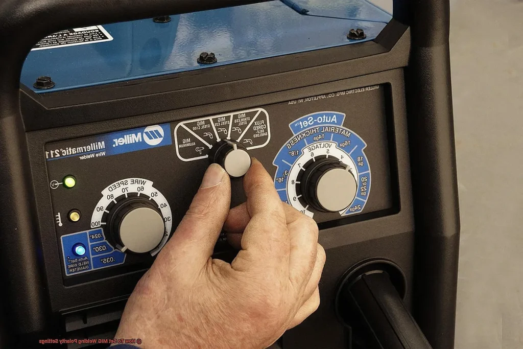
Tinkering with Your MIG Welder: Getting Great Welds Every Time
Ever stared at a MIG-welded seam that looks more like a bumpy, sputtering mess than a clean, strong joint? You're not alone. Getting that perfect bead often comes down to knowing exactly how to adjust your MIG welder for the job at hand. It’s less about having the fanciest machine and more about understanding the interplay between voltage, wire speed, and the material you're working with.
Manufacturer specifications confirm that proper settings are crucial, and achieving them consistently makes all the difference between a weld that holds and one that fails. For instance, according to Lincoln Electric's data as of 2026, specific voltage and wire speed combinations are recommended for different steel thicknesses to ensure optimal penetration and arc stability. Let’s break down how to get your welder dialed in.
Why Your MIG Welder Settings Matter
The quality of your welds hinges on a handful of core adjustments you make on your MIG welder. These aren't arbitrary numbers; they dictate the arc characteristics, heat input, and ultimately, how effectively the filler material fuses with the base metal. When these settings are off, you'll immediately see it in the weld’s appearance and, more importantly, its structural integrity.
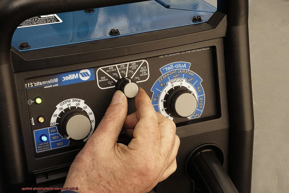
Think of it like this: too little heat and your weld won't penetrate, leaving it weak and superficial. Too much heat, and you risk burning through thin material, creating undercut, or causing excessive spatter that weakens the joint and makes a mess. Getting these settings right ensures a clean, deep fusion, creating a strong bond that's built to last. It’s the difference between a welded piece that looks professionally done and one that looks like it was tacked together in a hurry.
Understanding Your MIG Welder Controls
At its heart, a MIG welder works by feeding a continuously advancing wire electrode through a welding gun. This wire melts, becoming the filler metal that joins your pieces. The complexity and control come from managing the electrical arc between this wire and the workpiece, along with a shielding gas that protects the molten metal from atmospheric contaminants.
The primary controls you’ll interact with on most MIG welders are voltage and wire speed. These two work in tandem to manage the heat and arc characteristics. Beyond that, the type of wire you use and the shielding gas you’re running are critical factors that influence the optimal settings.
Voltage: The Arc's Personality
Voltage determines the arc length and, consequently, the "personality" of your weld. It's usually controlled by a knob with settings that might be numbered (like 1-10) or descriptive (like "Low," "Medium," "High"). Manufacturer specifications confirm that voltage is a primary driver of deposited metal shape and penetration.
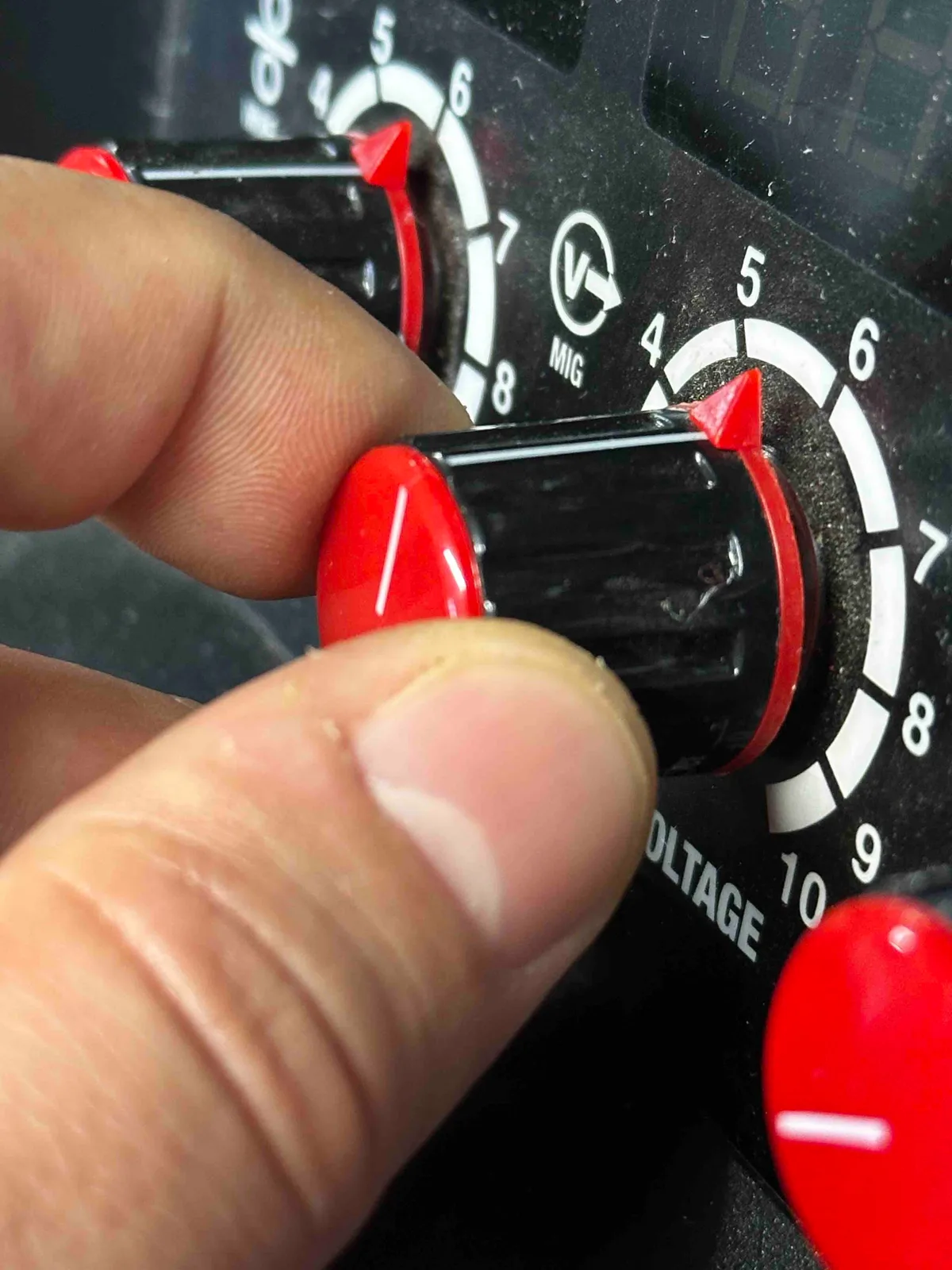
- Low Voltage: Results in a shorter, more concentrated arc and usually a narrower, deeper weld bead. If the voltage is too low, the arc might sound "poppy" or "stabby," and penetration will be poor.
- High Voltage: Creates a longer, more sweeping arc, leading to a wider, flatter weld bead. If the voltage is too high, you’ll likely see excessive spatter, and the bead might have undercut, where the base metal is melted away at the edges of the weld.
Matching your voltage to the wire feed speed and material thickness is key to achieving a smooth, stable arc and a well-formed weld bead.
Wire Speed: Driving the Heat
Wire speed, often measured in Inches Per Minute (IPM), directly controls the amount of amperage (electrical current) delivered to the weld. Essentially, the faster the wire feeds, the more material is melted, and the more heat is generated. This is often the go-to adjustment for controlling penetration and weld size when your voltage is in the right ballpark.
For example, in our research on welding settings for stick welding, we found that amperage (similar to wire speed in MIG) is paramount for controlling heat. A common range for .035-inch solid steel wire on mild steel might be anywhere from 100 to 250 IPM, depending on the material thickness and desired outcome.
- High Wire Speed: Delivers more amps, resulting in deeper penetration and a larger weld puddle. This is good for thicker materials.
- Low Wire Speed: Delivers fewer amps, leading to shallower penetration and a smaller, more controlled weld bead. This is essential for working with thinner metals.
Finding the right balance between voltage and wire speed is the fundamental step in getting your MIG settings right.
Gas Flow: The Invisible Shield
Shielding gas is a critical component of MIG welding, acting like an invisible umbrella over your molten weld puddle. It protects the hot metal from oxygen and nitrogen in the air, which would otherwise cause porosity (tiny holes) and significantly weaken the weld. The most common shielding gas for mild steel MIG welding is a mix of Argon and CO2, often an 80/20 blend.
Manufacturer specifications for gas flow rate typically range from 20 to 25 cubic feet per hour (CFH) for most general welding applications. Running too little gas leaves the weld vulnerable to contamination and spatter.
- Too Little Gas: Causes porosity, a rough arc, and a weaker weld. You might see a "whistling" or sputtering sound at the gun.
- Too Much Gas: Can cause turbulence, drawing in atmospheric contaminants and also leading to porosity and reduced weld quality. It also wastes gas unnecessarily.
Ensuring your gas regulator is set correctly, usually around 20-25 CFH, is vital for a clean, stable weld.
Common Problems and How to Fix Them
Even with the right equipment, you'll encounter issues that require adjustment. Understanding what common weld defects look like and what causes them is your first line of defense against a bad weld. These problems usually point directly to settings that are out of balance.
Dodging the Spatter Storm
Excessive spatter is one of the most common frustrations for MIG welders. It's those little droplets of molten metal that fly off the arc and stick to your workpiece and surrounding areas. While some minimal spatter is normal, a lot of it indicates that something's off with your settings or your process.
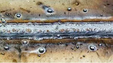
Our research indicates that high voltage is frequently the culprit behind excessive spatter. When the voltage is too high for the wire feed speed, the arc becomes unstable, throwing molten metal. Also, incorrect polarity settings can lead to a massively spattery weld. For common solid steel wire, the welding gun should be on DCEN (Direct Current Electrode Negative), and the ground clamp on DCEP (Direct Current Electrode Positive).
If reversed, you'll get a severe spatter issue and a very poor weld. A quick check of the polarity settings on your welder is always a good first step if you're seeing significant spatter.
Welding Too Wide or Too Narrow?
The shape and width of your weld bead tell a story about your settings. A weld that's too wide and flat might look lazy, while one that's too narrow and ropey suggests you're not getting enough heat or fusion.
- Wide, Flat Bead: This typically signals that your voltage is set too high. The arc is spreading out too much, and it's not concentrating the heat effectively. Lowering the voltage will often bring the bead profile back to a more desirable, slightly convex shape.
- Narrow, Ropey Bead: Usually means your voltage is too low, or your wire speed is too low for the chosen voltage. The arc isn't energetic enough, resulting in a bead that sits on top of the metal rather than fusing into it. Increasing wire speed, and potentially voltage slightly to match, will help.
Finding the sweet spot where the bead is neither too wide nor too narrow, and it melts smoothly into the base metal, is a key goal.
Getting the Right Penetration
Penetration is how deeply the weld metal fuses with the base metals. It's absolutely critical for weld strength, especially in structural applications. If your weld looks like it’s just sitting on the surface without melting into the parent material, you have a penetration problem.
The primary factors affecting penetration are the amount of heat (primarily controlled by wire speed and voltage) and your travel speed.
- Insufficient Penetration: This usually means you need more heat. Increase your wire speed incrementally. If the arc becomes too "poppy" or unstable, you may also need to slightly increase your voltage. Additionally, slow down your travel speed; moving too fast doesn’t give the heat enough time to melt into the base metal. Manufacturer specifications for materials like mild steel often recommend higher wire speeds for thicker sections.
- Excessive Penetration (Burn-Through): This means you have too much heat for the material thickness, or you're moving too slowly. Reduce your wire speed significantly. If you're on thinner material, you might also need to lower your voltage. Always consult available welding chart mig wire guides for recommended settings for specific material gauges.
Step-by-Step: Adjusting for Different Materials and Thicknesses
Adjusting your MIG welder isn't a one-size-fits-all affair. It's a dynamic process that requires you to consider the material you're welding, its thickness, and the type of wire and gas you're using. A good starting point is always the manufacturer's recommended settings chart, often found inside the welder's cabinet door or in the owner's manual.
These charts provide a baseline, but they are not gospel. They are designed to get you in the "ballpark." From there, you’ll fine-tune based on what you’re seeing and hearing. For context, even common materials like mild steel require vastly different settings for 16-gauge sheet metal versus 1/4-inch plate.
Starting with the Right Baseline Settings
- Identify Your Material: What are you welding? Mild steel, stainless steel, aluminum? This dictates wire and gas choices.
- Measure Thickness: Use a caliper or measurement tool to determine the exact thickness of the metal. This is the most crucial variable for setting your welder.
- Consult the Chart: Find the recommended voltage and wire speed (or amperage) for your material thickness and wire diameter from your welder’s chart. For example, a .030-inch wire on 1/8-inch (0.125-inch) mild steel might suggest a voltage around 18V and a wire speed of approximately 200 IPM.
- Set Up Your Gas: Ensure your shielding gas bottle is open and the regulator is set to the recommended flow rate (typically 20-25 CFH).
- Initial Weld: Make a short test weld on a piece of scrap metal that matches your project material. Listen to the sound of the arc, it should be a consistent, smooth buzz or sizzle, not a crackle or pop.
- Observe the Bead: Look at the weld. Is it too wide, too narrow, or just right? Is there excessive spatter? Is it penetrating properly?
- Adjust One Variable at a Time: Based on your observation, make a small adjustment to either voltage or wire speed. If it's too narrow, increase wire speed. If it's too wide and flat, decrease voltage. Make another small weld and observe again. Repeat this process until you achieve a satisfactory weld.
Troubleshooting Unstable Arcs and Other Annoyances
An unstable arc means the electrical current isn't flowing smoothly between the wire and the workpiece. This can feel erratic, sound buzzy or crackly, and produce inconsistent welds with porosity and spatter. There are several common reasons for this, and they often relate to connections or the condition of your consumables.
- Dirty Metal: The most frequent offender behind an unstable arc is dirty base metal. Rust, paint, oil, or any other contaminant will interfere with a clean electrical contact and disrupt the arc. Always clean your joint area with a wire brush and degreaser before welding. If you're welding previously used metal, a thorough cleaning is non-negotiable.
- Bad Connections: Loose connections anywhere in the welding circuit can cause instability. This includes the ground clamp connection to the workpiece and the welder, as well as the power connections within the machine. A poor ground, in particular, significantly impedes the flow of current and can lead to a weak, unstable arc.
Checking Your Ground and Connections
Your ground clamp is essential for completing the electrical circuit. If it's not making good, solid contact with clean metal, you'll experience arc instability, poor penetration, and excessive spatter.
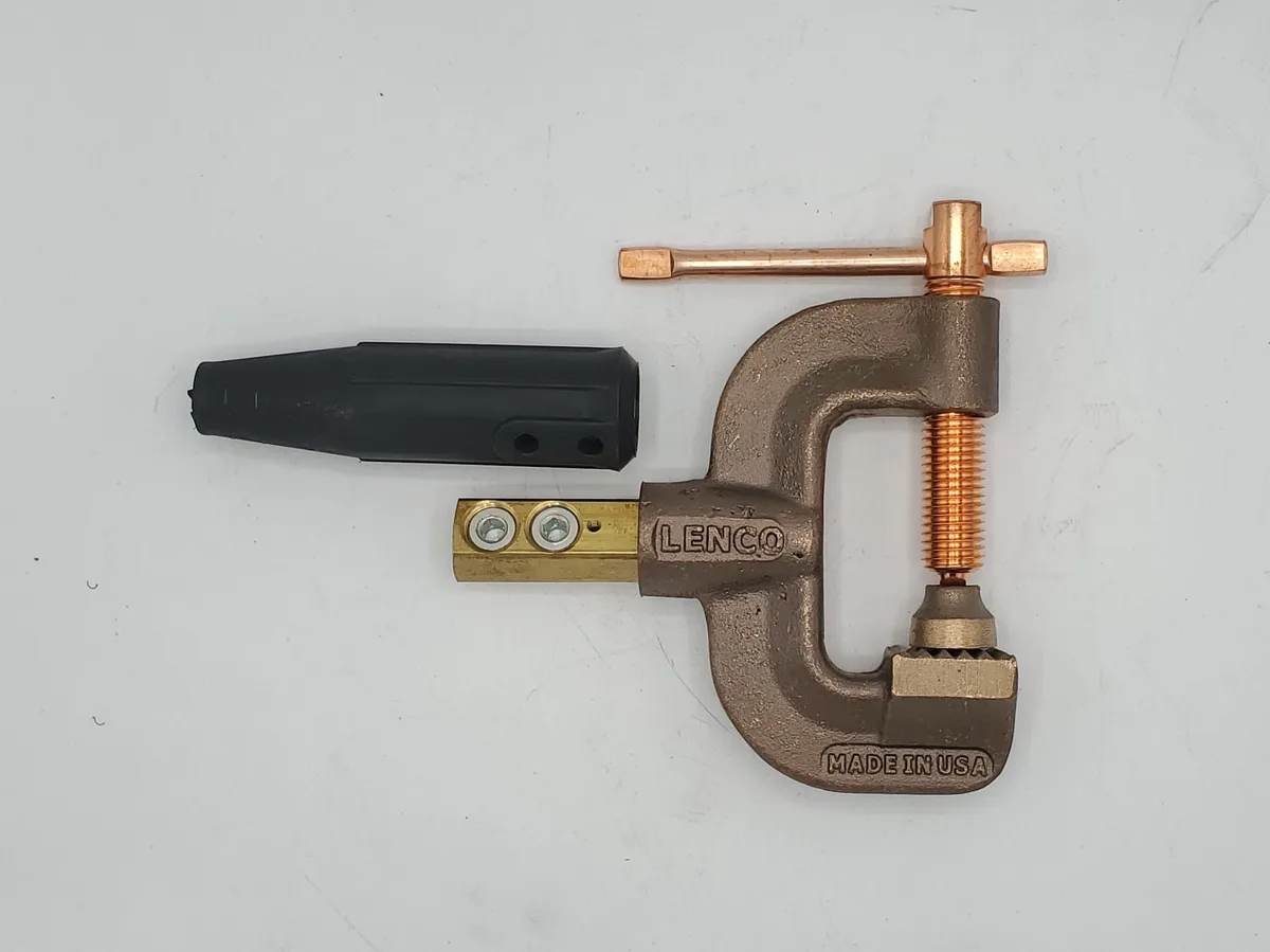
- Secure Attachment: Ensure the ground clamp is firmly attached to your workpiece. Don't just clip it onto a painted surface; it needs to bite into bare metal.
- Clean Surface: If the metal is painted, coated, or heavily corroded, use a wire brush or an angle grinder to remove the surface layer and expose clean metal for the clamp. A clean connection is paramount for a strong, stable arc.
- Direct Path: Try to keep the ground cable as short as practically possible and avoid kinks. A long, coiled cable can create electrical resistance.
Beyond the ground clamp, check that the welding gun is securely connected to the MIG welder, and that the power cord is also firmly seated. These simple checks can resolve many arc instability issues quickly.
The Scoop on Wire Stickout and Tip Condition
The contact tip is what transfers electricity to the welding wire and guides it into the weld puddle. Its condition and how far the wire extends from it have a significant impact on arc stability and weld quality.
- Wire Stickout: This is the length of wire that protrudes from the tip of the welding gun. For most solid wire MIG welding, a stickout of 1/2 inch to 3/4 inch (approximately 13-19mm) is generally recommended. Too little stickout can cause the arc to be too concentrated and the tip to become fouled quickly, while too much stickout exposes the wire to the atmosphere longer, leading to weld defects and spatter.
- Contact Tip Condition: The tip can become worn, enlarged, or clogged with spatter over time. A worn tip will enlarge the nozzle opening, leading to inconsistent wire feeding and arc wandering. A tip clogged with spatter can prevent the wire from feeding smoothly and also disrupt the electrical contact. Regularly inspect and clean the contact tip. If it appears worn or damaged, replace it. Contact tips are inexpensive consumables and are critical for consistent performance.
Pro Tips for Fine-Tuning Your MIG Weld
Beyond the basic settings, there are a few subtle techniques and observations that can elevate your MIG welding from good to great. These are the kinds of things experienced welders pick up over time.
Listen to Your Arc
The sound of a well-adjusted MIG arc is very distinctive. It should have a smooth, consistent hum or buzz, often described as sounding like bacon frying right. If you hear excessive crackling, popping, or a spitting, unstable sound, it’s a clear indication that something is out of adjustment.
- Too much popping: Often means voltage is too high, or you have too much spatter.
- A sharp, crackling sound: Can indicate insufficient voltage or poor shielding gas coverage.
Paying attention to the audible feedback from your arc can tell you a lot about what adjustments you might need to make.
Cleanliness is Key
This can’t be stressed enough: clean metal, clean consumables, and a clean workspace lead to better welds.
- Metal Prep: Always use a stainless steel wire brush and a degreaser to clean the area you're about to weld. Remove any rust, paint, oil, grease, or dirt. This ensures good electrical conductivity and prevents contaminants from entering your weld.
- Consumables: Keep your contact tips clean and free of spatter. Wipe down your welding gun nozzle periodically to remove any buildup.
- Workspace: A cluttered workspace can lead to accidents and make it harder to achieve a good weld. Keep your area tidy and free of flammable materials.
Safety First: Essential Warnings for MIG Welding Adjustments
When you're adjusting a MIG welder, you're working with electricity, high temperatures, and potentially hazardous gases. Safety should always be your top priority. Always consult your welder's manual for specific safety guidelines.
- Electrical Hazard: Always ensure the welder is unplugged when making internal adjustments or replacing parts like the contact tip or nozzle. Even when unplugged, capacitors can hold a charge, so exercise caution.
- Heat and Fire Hazard: Molten metal and the welding arc generate extreme heat. Ensure you're wearing appropriate personal protective equipment (PPE), including welding gloves, a welding jacket, and sturdy footwear. Keep flammable materials away from your welding area.
- Fume Hazard: Welding produces hazardous fumes. Always ensure you are welding in a well-ventilated area, or use an appropriate fume extraction system. Wear a welding helmet with an auto-darkening lens to protect your eyes from intense arc rays.
- Gas Cylinder Safety: Shielding gas cylinders are under high pressure. Handle them with care, ensure they are properly secured, and never tamper with the valve or regulator assembly. If you're unsure about regulator use, consult the manufacturer's documentation.
Which MIG Welder Settings Are Best for Thin Metal?
Welding thin metal, like automotive body panels or sheet steel under 18 gauge, presents a unique challenge because it's easy to burn through. The goal here is to use just enough heat to fuse the metals without melting holes. This generally means lower voltage and precise wire speed control.
- Lower Voltage: Start with a lower voltage setting. For very thin materials (24-20 gauge), you might be in the lower end of your machine's range, perhaps 15-17 volts.
- Lower Wire Speed: Crucially, your wire speed will be significantly lower than for thicker materials. This directly controls amperage. For .023 or .030 wire, you might be looking at 100-150 IPM or even less, depending on material thickness and your specific welder. The welder's chart for thin materials is your best friend here.
Our research indicates that welding stainless steel with a MIG welder often requires slightly different settings than mild steel, with some manufacturers recommending a slightly higher voltage range for stainless, even on thinner gauges, to achieve proper fusion.
What About Adjusting for Thicker Steel?
When you're working with thicker steel, like frame components or structural steel, you need to introduce more heat to achieve adequate penetration. This means increasing both voltage and wire speed. Over-penetration isn't typically a concern here, as the material is robust enough to handle it.
- Higher Voltage: You'll likely be in the mid-to-upper range of your machine's voltage settings, possibly 18-22 volts or more, depending on the thickness.
- Higher Wire Speed: To match the higher voltage, you'll need to increase wire speed considerably. For .035 wire on 1/4-inch steel, wire speeds could easily exceed 300 IPM. It's about finding that smooth arc sound again, but with more power behind it. You might also consider a slightly richer shielding gas blend for thicker materials to help with puddle control.
How to Tell If Your Wire Feed Speed is Correct
Your wire feed speed is directly related to amperage, and getting it right is crucial for controlling how deep your weld penetrates and how wide the bead is. If your wire feed speed is too high or too low, your welds will suffer.
- Too High: You’ll likely experience excessive penetration, burn-through on thinner materials, a very wide bead, and possibly a spattering arc if the voltage isn't balanced. The sound might be a very aggressive, loud buzz.
- Too Low: Expect shallow penetration, a narrow and ropey bead that sits on top of the metal, and potentially an unstable arc. The sound might be flatter or more crackly.
To test the speed, use your welder’s built-in settings chart or an online calculator if available. Then, make a test weld and observe the results. If the penetration is too shallow, increase wire speed by small increments (e.g., 10-20 IPM at a time) and re-test until you get the desired depth without sacrificing weld appearance. If you're burning through, decrease the speed.
It's a balancing act, and finding that sweet spot where the arc sound is smooth and the bead profile is correct is the goal.


