Getting the voltage and wire speed dialed in correctly is the difference between a smooth, consistent bead and a mess of spatter, porosity, or burn-through. Miller welders are known for their reliable performance, but even the best machine produces poor welds when the settings are off.
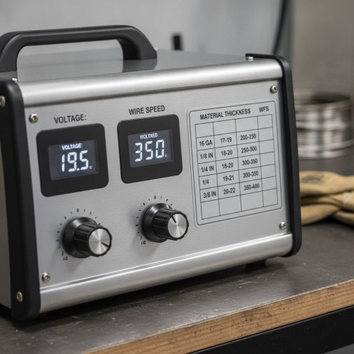
Miller MIG welders use a voltage and wire feed speed combination that varies by material thickness, wire diameter, and shielding gas. For mild steel with 0.030″ wire, typical settings range from 16–19V at 200–300 IPM for thin material (18–14 gauge), up to 21–25V at 300–450 IPM for thicker plate (3/16″ to 1/4″). Always start with the chart on the inside panel of your Miller welder as a baseline, then fine-tune from there.
Why Voltage and Wire Speed Work Together
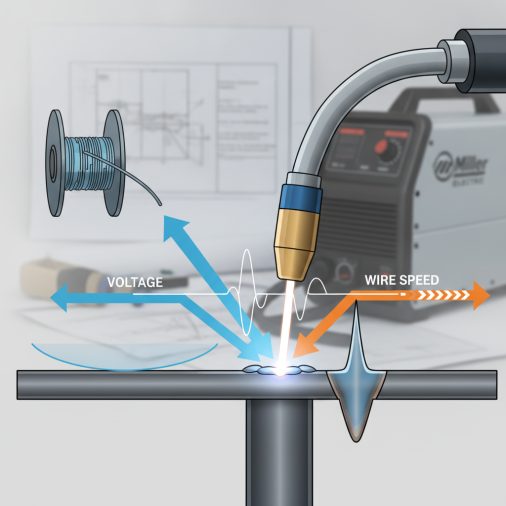
These two settings are not independent. Voltage controls arc length and the overall heat input, while wire feed speed (WFS) controls the deposition rate and, indirectly, the amperage.
Increase wire speed and you’re feeding more filler into the arc, which draws more amperage. Decrease voltage without adjusting wire speed and you’ll get stubbing — the wire pushing into the puddle before it melts. The goal is a balanced relationship between the two where the arc sounds like steady, frying bacon.
Most Miller machines in the Millermatic series, like the Millermatic 211 or Millermatic 255, have an Auto-Set feature that adjusts voltage and wire speed automatically based on wire diameter and material thickness. Even so, knowing the manual settings gives you the control to fine-tune beyond what automation provides.
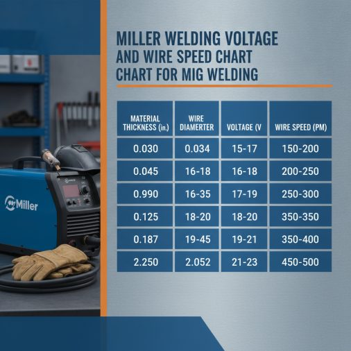
Miller MIG Welding Settings Chart — Mild Steel
The following chart covers common mild steel thicknesses using ER70S-6 wire with 75/25 Argon/CO₂ shielding gas. These are starting points — not absolute settings.
0.023″ Wire (Thin Sheet Metal)
Material Thickness
Voltage
Wire Feed Speed (IPM)
Amperage (Approx.)
24 gauge (0.024")
13–14V
100–130 IPM
30–50A
22 gauge (0.030")
14–15V
130–160 IPM
45–65A
20 gauge (0.036")
15–16V
155–185 IPM
60–80A
18 gauge (0.048")
16–17V
175–210 IPM
75–95A
0.030″ Wire (Light to Medium Gauge)
Material Thickness
Voltage
Wire Feed Speed (IPM)
Amperage (Approx.)
18 gauge (0.048")
16–17V
200–240 IPM
75–100A
16 gauge (0.060")
17–18V
230–270 IPM
90–115A
14 gauge (0.075")
18–19V
260–300 IPM
110–130A
1/8" (0.125")
19–21V
280–330 IPM
130–155A
3/16" (0.188")
21–23V
320–380 IPM
155–185A
0.035″ Wire (Medium to Heavy Material)
Material Thickness
Voltage
Wire Feed Speed (IPM)
Amperage (Approx.)
1/8" (0.125")
18–20V
200–250 IPM
130–160A
3/16" (0.188")
20–22V
250–310 IPM
160–195A
1/4" (0.250")
22–24V
300–375 IPM
190–230A
5/16" (0.313")
23–25V
340–410 IPM
220–260A
0.045″ Wire (Heavy Fabrication)
Material Thickness
Voltage
Wire Feed Speed (IPM)
Amperage (Approx.)
1/4" (0.250")
22–24V
180–240 IPM
200–250A
3/8" (0.375")
24–26V
240–320 IPM
250–310A
1/2" (0.500")
26–29V
310–400 IPM
300–375A
How to Read and Use These Settings Correctly
A common mistake is treating chart values as exact settings. They are reference points, not final answers. Material condition, joint type, welding position, and even ambient temperature all affect how a weld responds.
Here’s how to work from the chart to a real weld:
1. Select your wire diameter based on material thickness. Thinner wire for thin material, thicker wire for structural or heavy plate.
2. Find the closest material thickness in the chart and note the voltage and WFS range.
3. Set your welder to the middle of the range — not the upper or lower extreme.
4. Run a test bead on scrap material of the same type and thickness.
5. Listen to the arc. A smooth, consistent crackle means you’re close. Popping and spattering usually means wire speed is too high or voltage too low. A hissing, hollow arc typically indicates voltage too high.
6. Inspect the bead profile. Good fusion, flat to slightly convex profile, and no undercut at the toes means settings are dialed in.
If you’re new to reading chart values or want to understand the logic behind them in more depth, this breakdown of MIG welding wire speed and voltage charts covers the relationship between settings and weld outcomes clearly.
Settings for Stainless Steel and Aluminum
Mild steel is the most common use case, but Miller welders are frequently used on stainless and aluminum as well. Settings differ significantly from mild steel, so using the wrong chart leads to poor fusion or burn-through.
Stainless Steel (ER308L or ER316L wire, 98% Argon / 2% CO₂ or tri-mix gas):
Material Thickness
Wire Diameter
Voltage
Wire Feed Speed (IPM)
16 gauge
0.030"
16–18V
200–250 IPM
1/8"
0.030"
18–20V
250–300 IPM
3/16"
0.035"
20–22V
270–330 IPM
Stainless retains heat much more than mild steel, so keep travel speed up and avoid excessive heat input. For a complete look at gas selection and bead quality on stainless, the MIG welding stainless steel settings guide goes into the practical details.
Aluminum (ER4043 or ER5356 wire, 100% Argon):
Material Thickness
Wire Diameter
Voltage
Wire Feed Speed (IPM)
1/8"
0.030"
18–20V
350–450 IPM
3/16"
0.035"
20–22V
400–520 IPM
1/4"
0.035"
22–24V
480–580 IPM
Aluminum requires much higher wire feed speeds compared to steel at similar thicknesses due to lower melt temperature and higher thermal conductivity. Using a spool gun like the Miller Spoolmate 100 Series is strongly recommended for aluminum — it nearly eliminates the bird-nesting and feed issues that plague standard push-pull setups with soft aluminum wire. For a more detailed breakdown of aluminum-specific settings, the aluminum MIG welding wire speed and voltage chart is worth referencing.
Shielding Gas and Its Effect on Voltage Settings
Shielding gas selection directly affects how your settings perform. The same voltage and WFS that produce a clean weld with 75/25 Argon/CO₂ will run hotter and spatter more with 100% CO₂.
Gas Mix
Arc Character
Voltage Adjustment
Best For
75/25 Ar/CO₂
Smooth, stable
Baseline
Mild steel, general fabrication
90/10 Ar/CO₂
Cleaner, slightly hotter
Lower by 0.5–1V
Sheet metal, cleaner welds
100% CO₂
More aggressive, spatter
Raise by 1–2V
Deep penetration, outdoor work
100% Argon
Very fluid, less penetration
Lower by 1–2V
Aluminum only
98/2 Ar/CO₂ or Tri-mix
Smooth, low spatter
Slight reduction
Stainless steel
When switching gas mixes, always re-test your settings on scrap before welding on a real joint.
Welding Position Adjustments
Flat and horizontal positions use the standard chart settings. When you change position, you typically need to reduce heat input to manage the puddle.
– Vertical up: Reduce voltage by 1–2V and slightly lower wire speed. Keep travel speed consistent and use a weave or triangle pattern.
– Vertical down: Use for thin material only. Keep settings close to flat but reduce wire speed slightly. Travel faster than vertical up.
– Overhead: Drop voltage by 1–2V and reduce wire speed by 10–15%. Smaller puddle is easier to control.
Position welding also requires solid technique. If you’re working on vertical joints and struggling with puddle control, the guide on how to weld vertical MIG covers the techniques that make positional work manageable.
Troubleshooting Common Setting Problems
Even with a good starting point from the chart, real welds don’t always go smoothly. Here’s what the symptoms tell you:
Excessive spatter:
– Voltage too low for the wire speed being used
– Increase voltage by 0.5–1V at a time, or reduce wire speed slightly
– Check gas flow — low coverage causes spatter regardless of settings
Wire stubbing into the puddle:
– Voltage too low, arc can’t maintain itself
– Increase voltage incrementally until stubbing stops
Burn-through on thin material:
– Voltage too high or travel speed too slow
– Drop voltage 1V, increase travel speed, or use a stitch weld pattern
Porosity in the weld:
– Usually a shielding gas issue (low flow, contamination, draft)
– Can also indicate wet or contaminated base metal
– Verify gas flow rate (typically 20–25 CFH for MIG) before adjusting electrical settings
Convex, ropy bead with poor tie-in:
– Voltage too low relative to wire speed
– Weld isn’t fusing properly into the base metal at the toes
For a deeper look at what causes poor weld appearance and how to diagnose it, the article on most common MIG welding mistakes covers the patterns most welders run into repeatedly.
Reducing spatter specifically is also worth focusing on — reducing spatter in MIG welding involves both settings adjustments and technique changes that work together.
How Wire Diameter Affects Your Settings Range
Wire diameter is the most fundamental variable in setting selection. Choosing the wrong wire size for your material limits what your settings can do, regardless of how much you adjust voltage or wire speed.
– 0.023″ — best for 24 gauge to 18 gauge sheet metal; very forgiving on thin material
– 0.030″ — versatile range covering 18 gauge to 3/16″; the most common all-purpose choice for home shops and automotive work
– 0.035″ — suited for 1/8″ and up; the standard wire for structural and fabrication work
– 0.045″ — heavy fabrication and structural work on 1/4″ plate and above; requires a higher-output machine
If you’re unsure about wire selection, the guide on what size MIG welding wire to use breaks down the decision by application.
FAQ
What is the correct wire feed speed for 1/4″ mild steel with 0.035″ wire on a Miller welder?
For 1/4″ mild steel using 0.035″ ER70S-6 wire and 75/25 Ar/CO₂, a good starting range is 300–375 IPM at 22–24 volts. Set the machine to the middle of that range, run a test bead on scrap, and adjust from there based on how the arc sounds and how the bead profile looks.
Why does my Miller welder sound rough and produce heavy spatter even when I follow the chart?
Rough arc and heavy spatter usually point to one of three things: voltage set too low for the wire speed, shielding gas issues (contamination, low flow, or wrong mix), or dirty/rusty base metal. Verify your gas flow is 20–25 CFH, check the nozzle for blockage, clean the base metal, then increase voltage by 0.5–1V and retest.
Does the Miller Auto-Set feature replace manual voltage and wire speed adjustments?
Auto-Set provides a reliable starting point based on wire diameter and material thickness, and it’s accurate enough for most standard mild steel work. However, it doesn’t account for joint type, welding position, surface condition, or gas mix variations. For critical work or non-standard situations, manual fine-tuning produces better results.
How do I calculate the wire feed speed if I don’t have a chart for my exact material thickness?
A practical method is to use the general rule that amperage roughly equals wire feed speed divided by a constant based on wire diameter — approximately 1 inch per amp for 0.030″ wire, and about 1.5 inches per amp for 0.035″ wire. Alternatively, the article on how to calculate wire feed speed in MIG welding walks through the math step by step.
What happens if wire feed speed is too high relative to voltage?
The wire feeds faster than the arc can melt it, causing the wire to stub into the puddle. You’ll hear popping and see the wire physically pushing against the workpiece before burning. The fix is either increasing voltage or reducing wire speed — usually both in small increments until the arc stabilizes.
Can I use the same voltage and wire speed settings for flux core wire as solid wire?
No. Flux core wire (FCAW) requires higher voltage and generally higher wire speed compared to solid MIG wire at similar thicknesses. It also typically uses CO₂ or 75/25 gas (or no gas for self-shielded wire). A flux core MIG welding settings chart uses a different set of values than solid wire charts.
How much does material surface condition affect voltage and wire speed settings?
More than most welders expect. Mill scale, rust, paint, and galvanizing all disrupt arc stability and shielding gas coverage. These contaminants can cause the same symptoms as incorrect settings — spatter, porosity, and poor fusion — making it harder to identify the real cause. Clean base metal always produces more predictable results from a given set of chart values.
The Miller voltage and wire speed chart is your starting point, not your endpoint. Every weld variable — metal thickness, wire diameter, gas mix, joint type, and position — pulls the ideal setting in a slightly different direction. Use the chart to get close, trust what you hear and see on the bead, and make small adjustments until the arc settles into that steady, confident crackle that signals everything is working together correctly.