
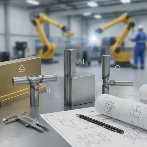
You’re looking at a fabrication drawing and see an arrow, a horizontal line, and a series of numbers and letters clustered around it. If you don’t know how to read weld symbols, that drawing might as well be in a foreign language.
Weld drawing symbols are a standardized shorthand used on engineering and fabrication drawings to communicate every detail of a required weld — including the joint type, weld size, length, location, finish method, and any special instructions — without written notes cluttering the blueprint. In most countries, these symbols follow either the American Welding Society (AWS) standard or the ISO standard, and the two systems differ in meaningful ways.
Why Weld Symbols Matter on the Shop Floor
A fabrication drawing has to communicate clearly across engineering, inspection, and production. Weld symbols eliminate ambiguity. They tell the welder exactly where to weld, what type of joint to use, how large the weld should be, and whether any post-weld finishing is required.
Misreading a symbol can result in the wrong joint type, inadequate weld size, or a weld placed on the wrong side of the joint. On structural, pressure, or safety-critical work, that kind of error can have serious consequences. Reading weld symbols accurately is a core fabrication skill.
The Reference Line: The Foundation of Every Symbol
Every weld symbol is built around a horizontal reference line. This line is the backbone from which all other information hangs. An arrow connects the reference line to the actual joint location on the drawing.
The arrow side of the reference line is the side closest to the arrow. The other side is called the other side. Weld information placed below the reference line applies to the arrow side of the joint. Information placed above the line applies to the other side.
A tail may be added to the end of the reference line opposite the arrow. The tail is used to reference a welding procedure specification (WPS), a note, or a special process instruction. If there is no tail, it simply means no special reference is needed.
The Weld Symbol Versus the Welding Symbol
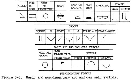
This distinction trips up many beginners. The weld symbol is the small graphic shape that identifies the type of weld — for example, a triangle for a fillet weld or a V-shape for a groove weld. The welding symbol is the complete assembly: the reference line, arrow, weld symbol, dimensions, and any supplementary data all together.
Calling the entire assembly simply “the weld symbol” is common in shops, but understanding the technical distinction helps when studying drawings in detail. The complete guide to reading welding symbols covers the full range of symbol types and their placements.
Common Weld Symbols and What They Represent
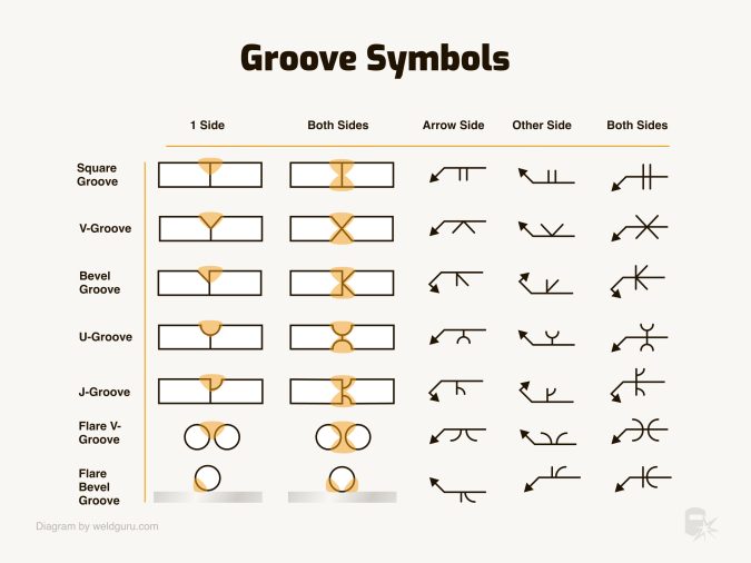
The most frequently used weld symbols each correspond to a specific joint geometry. Here are the most common ones:
- Fillet weld — represented by a right triangle. Used for lap joints, T-joints, and corner joints where two members meet at an angle.
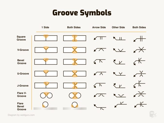
- Square groove weld — two parallel vertical lines. Used for butt joints in thinner material with no edge preparation.
- V-groove weld — a V-shape opening upward. Indicates a beveled butt joint on both members.
- Bevel groove weld — a single angled line with a vertical line. Only one member is beveled.
- U-groove weld — a U-shape. Used for deeper joints where the curved groove reduces filler metal volume.
- J-groove weld — similar to U-groove but applied to one side only.
- Plug weld — a circle. Indicates a weld made through a hole in one member to join it to the member beneath.
- Slot weld — an elongated version of the plug symbol.
- Spot weld — a circle with no reference line dash, often used for resistance welding.
- Seam weld — two parallel horizontal lines through a circle.
- Back or backing weld — a semicircle placed on the opposite side of a groove weld.
- Surfacing weld — a flat wavy line. Indicates built-up weld metal applied to a surface, not a joint.
Reading the Dimensions on a Weld Symbol
Dimensions appear to the left and right of the weld symbol on the reference line. The specific position of each number carries meaning, and mixing them up leads to real fabrication errors.
Fillet Weld Dimensions
For a fillet weld, the number to the left of the triangle is the weld size — the leg length of the fillet, typically in inches or millimeters. The number to the right is the weld length. A hyphen followed by another number to the right indicates pitch, meaning the center-to-center spacing of intermittent welds.
For example, a symbol showing 3/8 – 2 – 6 means a 3/8-inch fillet, 2 inches long, placed every 6 inches on center.
Groove Weld Dimensions
Groove welds carry more dimensional detail. The depth of preparation appears in parentheses to the left of the symbol. The number outside parentheses, also to the left, is the effective throat. The groove angle may appear inside the symbol. Root opening — the gap between members — appears at the base of the V or bevel.
Supplementary Symbols That Modify a Weld
Several supplementary symbols appear alongside the basic weld symbol to add important instructions.
- Weld all around — a small circle placed at the junction of the arrow and reference line. Means the weld continues around the entire perimeter of the joint.
- Field weld — a filled (solid) flag at the junction of the arrow and reference line. Indicates the weld is to be made in the field, not in the shop.
- Melt-through — a filled semicircle on the opposite side from the weld symbol. Indicates complete joint penetration is required from one side.
- Contour symbols — a flat line, convex arc, or concave arc placed above the weld symbol indicates the required finished profile of the weld face.
- Finish symbols — a letter placed beside the contour symbol indicates how the surface should be finished. C means chipping, G means grinding, M means machining.
Both-Sides and All-Around Welds
When the same weld is required on both sides of a joint, the weld symbol appears both above and below the reference line. This is common on double-V groove joints and on both-sides fillet welds at a T-joint.
The weld-all-around circle tells the welder to continue without stopping around the full perimeter. This is common on tubular connections, pipe penetrations through gussets, and bracket attachments where an interrupted weld would create stress concentration points.
AWS Versus ISO Weld Symbols
AWS and ISO symbols share many concepts but differ enough to cause errors if a welder trained on one system reads drawings using the other.
| Feature | AWS (A2.4) | ISO (2553) |
|---|---|---|
| Arrow-side placement | Below reference line | Below reference line |
| Other-side placement | Above reference line | Above reference line |
| Fillet weld symbol | Right triangle | Two lines forming a right angle |
| Weld size position | Left of symbol | Left of symbol (leg size shown differently) |
| Field weld indicator | Filled flag | Not used in the same way |
| Tail usage | Common for process/WPS reference | Less common |
| Primary standard document | AWS A2.4 | ISO 2553 |
Always confirm which standard governs the drawing package before starting fabrication. This is especially important on international projects or when working with drawings from a different country or engineering firm.
Process Abbreviations in the Tail
When a specific welding process is required, the abbreviation appears in the tail of the welding symbol. AWS standard abbreviations are used in most North American shops.
- SMAW — Shielded Metal Arc Welding (stick)
- GMAW — Gas Metal Arc Welding (MIG)
- GTAW — Gas Tungsten Arc Welding (TIG)
- FCAW — Flux Cored Arc Welding
- SAW — Submerged Arc Welding
- OFW — Oxyfuel Welding
Some drawings use “RD” alongside a process abbreviation to indicate a specific weld type or reference drawing. The abbreviation RD on a MIG weld drawing has a specific meaning that can cause confusion when encountered for the first time.
CJP and PJP: Joint Penetration Terms
Two abbreviations appear frequently on groove weld symbols and affect how the joint must be welded and inspected.
CJP means Complete Joint Penetration. The weld must fuse through the full thickness of the joint. This is a structurally demanding requirement that often mandates back gouging, backing bars, or a demonstrated welding procedure. Ultrasonic or radiographic testing is commonly required on CJP welds in structural or pressure applications.
PJP means Partial Joint Penetration. The weld penetrates only to a specified depth, indicated by the dimension in parentheses on the symbol. PJP welds are acceptable in many applications but have reduced capacity compared to CJP welds.
Reading an Intermittent Fillet Weld Symbol
Intermittent welds appear as a series of short weld segments rather than a continuous bead. They reduce heat input, distortion, and filler metal consumption when continuous welds are not structurally required.
The symbol shows the weld size, the segment length, and the pitch separated by a hyphen. Chain intermittent welds place segments on both sides of the joint in line with each other. Staggered intermittent welds offset the segments so they alternate sides. A staggered pattern is indicated when the symbols above and below the reference line are offset from each other rather than aligned.
Safety When Working From Weld Drawings
A weld symbol on a drawing is a binding instruction, not a suggestion. Fabricating a weld that does not match the specified size, type, or location — whether from misreading the symbol or skipping steps — can create an unsafe structure that passes visual inspection but fails under load.
On regulated work — structural steel, pressure vessels, pipelines, lifting equipment, vehicle components — welding must follow a qualified Welding Procedure Specification (WPS). If a symbol is unclear or appears inconsistent with the drawing geometry, stop and get clarification from the engineer or drawing originator before welding.
Eye protection, appropriate PPE, and adequate ventilation remain essential regardless of what the symbol says. The symbol governs the weld; shop safety rules govern the process of making it.
Frequently Asked Questions
What is the difference between a weld symbol and a welding symbol?
The weld symbol is the small graphic that shows the weld type, such as a triangle for a fillet or a V-shape for a groove. The welding symbol is the complete assembly on the drawing, including the reference line, arrow, weld symbol, all dimensions, supplementary symbols, and the tail. The weld symbol is one component of the larger welding symbol.
What does the triangle on a weld drawing mean?
A right triangle on the reference line is the fillet weld symbol. The number to its left indicates the weld leg size. Fillet welds are among the most common joint types in fabrication and are used on T-joints, lap joints, and corner joints. The position of the triangle above or below the reference line determines which side of the joint receives the weld.
What does a circle on the welding symbol mean?
A small circle placed at the junction of the arrow and the reference line means “weld all around.” It tells the welder to run a continuous weld completely around the joint perimeter. A circle used as the primary weld symbol — not at the junction — generally indicates a plug weld or, in resistance welding, a spot weld. Context and position determine which meaning applies.
What does CJP mean on a weld drawing?
CJP stands for Complete Joint Penetration. It means the weld must fuse through the entire thickness of the joint with no unfused root. CJP welds are structurally demanding, often require back gouging or backing, and may need nondestructive examination to verify full penetration. The drawing or applicable standard will specify the inspection requirements.
How do I know which side of the joint to weld on?
The position of the weld symbol relative to the reference line determines the weld side. A symbol below the reference line means weld on the arrow side — the side the arrow points to. A symbol above the line means weld on the other side. A symbol both above and below means both sides of the joint require welds.
Are AWS and ISO weld symbols interchangeable?
They are not fully interchangeable. The two systems share similar logic but differ in how symbols are drawn, how dimensions are positioned, and how certain joint types are represented. Using AWS training to interpret an ISO drawing — or vice versa — can produce errors. Always confirm which standard applies to the drawing package before fabrication begins.
Can a welder interpret weld symbols without formal training?
Some basic symbols are straightforward to pick up on the job, but formal training in weld symbol reading significantly reduces the risk of misinterpretation. On structural, pressure, or regulated work, misreading a symbol can result in an unsafe fabrication that looks acceptable on the surface. Most welding certification programs and apprenticeships include blueprint and symbol reading as core components.
Putting It All Together on the Shop Floor
Reading weld drawing symbols accurately is not optional on professional fabrication work. The reference line, arrow, weld symbol, dimensions, and supplementary information each carry a specific meaning, and ignoring or misreading any part changes the weld.
Start by identifying the reference line and arrow, then determine the arrow side and other side. Read the weld symbol shape to identify the joint type, check the dimensions to the left and right, and look for supplementary symbols. Confirm the applicable standard — AWS or ISO — before interpreting unfamiliar symbols.
When the drawing specifies a process, size, penetration requirement, or finish that falls outside your procedure or qualification, get clarification. Fabricating to an incorrect interpretation costs more to correct than the time it takes to ask the question first.


