
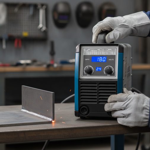
You’re standing at your MIG welder, looking at a piece of steel, and the question hits: what amperage should I actually be running? Too low and you get cold, incomplete fusion. Too high and you burn through or warp the metal.
MIG welding amperage is primarily determined by material thickness. As a general starting point, most welders use roughly 1 amp per 0.001 inch of material thickness for steel — so 18-gauge steel (approximately 0.047 inches) runs around 70–90 amps, while 1/4-inch steel may need 180–220 amps or more. Wire diameter, shielding gas, joint type, welding position, and your specific machine all affect where the ideal amperage actually lands.
Why Amperage Matters in MIG Welding
In MIG welding, amperage controls heat input. Higher amperage melts the base metal and wire faster, producing deeper penetration and a wider bead. Lower amperage keeps heat down, which matters for thin sheet metal where burn-through is a real risk.
Unlike stick welding, where you set amperage directly, MIG machines are primarily controlled by wire feed speed. Wire feed speed and amperage are directly linked — as you increase wire feed speed, amperage rises automatically. Voltage is adjusted separately and controls arc length and bead profile.
Understanding this relationship helps you read the MIG wire speed and voltage chart on your machine more effectively, because amperage, wire feed speed, and voltage all work together.
MIG Welding Amperage Chart by Material Thickness
The table below provides general starting-point ranges for solid MIG wire on mild steel using 75% Argon / 25% CO₂ shielding gas (C25) and DCEP polarity. These are not welding procedure specifications. Treat them as a baseline and fine-tune from there.
| Material Thickness | Wire Diameter | Approximate Amperage Range | Typical Voltage Range |
|---|---|---|---|
| 24 gauge (0.024 in / 0.6 mm) | 0.023 in | 30–50 A | 13–15 V |
| 20 gauge (0.036 in / 0.9 mm) | 0.023–0.030 in | 50–70 A | 14–16 V |
| 18 gauge (0.047 in / 1.2 mm) | 0.030 in | 70–90 A | 15–17 V |
| 16 gauge (0.062 in / 1.6 mm) | 0.030 in | 90–110 A | 16–18 V |
| 1/8 in (3.2 mm) | 0.030–0.035 in | 110–140 A | 17–19 V |
| 3/16 in (4.8 mm) | 0.035 in | 140–175 A | 18–21 V |
| 1/4 in (6.4 mm) | 0.035–0.045 in | 175–220 A | 20–23 V |
| 3/8 in (9.5 mm) | 0.045 in | 200–280 A | 22–26 V |
These ranges apply to flat or horizontal position welding. Overhead or vertical welding typically requires lower amperage to control puddle fluidity.
How Wire Diameter Affects Your Amperage Range
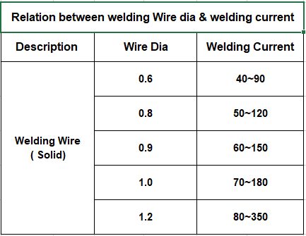
Wire diameter has a direct influence on the usable amperage window. Thinner wire carries a lower current capacity and is better suited to thin material. Thicker wire handles higher current and is more efficient on heavier sections.
- 0.023 in wire: Best for sheet metal under 18 gauge. Operates well at low amperages where larger wire would be difficult to control.
- 0.030 in wire: The most versatile size for light to medium fabrication, roughly 18 gauge up to 3/16 inch.
- 0.035 in wire: A common choice for structural work, trailers, and general fabrication in the 1/8 to 3/8-inch range.
- 0.045 in wire: Suited to heavier plate on industrial machines with higher output capacity.
Running wire at the low end of its usable range produces an unstable arc. Running it at the high end can cause excessive spatter and poor bead shape. Matching wire diameter to the thickness range you weld most often gives you the best working window. For a more detailed breakdown, the guide on choosing the right MIG welding wire size covers the selection process in full.
Material Type Changes the Starting Point

The chart above applies to mild steel. Stainless steel and aluminum have different thermal conductivity, melting points, and filler metal requirements that shift the amperage picture.
Stainless Steel
Stainless steel conducts heat more slowly than mild steel, which means heat builds up in the weld zone faster. This often means you can run slightly lower amperage compared to mild steel of the same thickness, or travel speed needs to increase to avoid sugaring on the back side. Shielding gas selection — typically a tri-mix or 98% Argon / 2% CO₂ — also affects arc behavior. You can find specific guidance on shielding gas choices for stainless MIG welding to pair with your amperage adjustments.
Aluminum
Aluminum has high thermal conductivity and a lower melting point, but it absorbs heat quickly across the part. Thicker aluminum often benefits from preheat, and the amperage ranges can differ significantly from steel. The aluminum MIG welding wire speed and voltage chart covers material-specific starting points in more detail.
How Welding Position Affects Amperage
Flat position allows the highest amperage because gravity assists puddle control. As position changes, reducing amperage helps prevent the puddle from sagging or dripping.
- Flat (1G/1F): Use the full starting-point range from the chart.
- Horizontal (2G/2F): Reduce amperage by approximately 5–10% as a starting adjustment.
- Vertical (3G/3F): Reduce amperage further. Vertical-up welding on thicker material still requires adequate heat for fusion, but puddle control becomes the priority.
- Overhead (4G/4F): Use the lower end of your amperage range and keep the puddle small.
Reading the Sticker Inside Your MIG Welder
Most MIG machines include a reference chart printed inside the wire feed door or on the front panel. This chart is calibrated to that specific machine and is one of the most reliable starting points available to you.
Machine charts typically show material thickness, suggested wire size, wire feed speed, and voltage. Since wire feed speed drives amperage on a MIG machine, matching the chart’s wire feed speed recommendation puts you close to the intended amperage for that setup.
Always cross-reference the machine chart with the wire manufacturer’s data sheet, especially when running a different wire classification than the machine was originally set up for. The guide on MIG wire welding chart settings explains how to interpret these references more accurately.
Variables That Shift Amperage From the Chart Value
Charts give you a starting point, not a guaranteed setting. Several real-world conditions push the ideal amperage up or down.
- Joint fit-up: Tight joints with good fit-up require less heat than joints with gaps. Gaps increase heat demand for fill and fusion.
- Surface condition: Mill scale, rust, paint, or galvanizing resist heat and can cause inconsistent fusion. Clean bare metal responds more predictably.
- Preheat: Preheated material already carries heat, so starting amperage may need slight reduction to avoid overheating.
- Travel speed: Slowing travel speed increases heat input at a given amperage. Increasing travel speed reduces effective heat input.
- Machine output accuracy: Older or lower-cost machines may not produce the exact amperage shown on the display. A clamp ammeter confirms actual output.
- Duty cycle: Running a machine near its rated capacity for extended periods can cause thermal rollback, effectively reducing output mid-weld.
Amperage and Common MIG Weld Defects
Incorrect amperage is one of the most common causes of weld defects. Recognizing the symptoms helps you adjust in the right direction.
| Symptom | Likely Cause | Adjustment |
|---|---|---|
| Cold lapping, lack of fusion | Amperage too low | Increase wire feed speed (amperage) |
| Burn-through, hole in base metal | Amperage too high for thickness | Decrease wire feed speed or increase travel speed |
| Excessive spatter | Voltage too low for amperage, or amperage too high | Increase voltage slightly or reduce wire feed speed |
| Tall, narrow, convex bead | Voltage too low relative to amperage | Increase voltage to flatten and wet out the bead |
| Wide, flat, irregular bead | Voltage too high relative to amperage | Decrease voltage or increase wire feed speed |
| Porosity | Contamination or shielding gas issue, not amperage directly | Check gas flow, clean base metal, inspect nozzle |
If excessive spatter is a recurring problem, the detailed guide on reducing MIG welding spatter covers both settings-based and technique-based solutions.
Amperage for Automotive Sheet Metal
Automotive body panels and structural sections typically range from 18 gauge down to 22 gauge. This is where amperage control is most critical, because even a modest increase can blow through thin steel instantly.
For automotive work, 0.023-inch wire at 60–90 amps is a common working range. Short-circuit transfer mode is standard for this thickness. Tack welding in short intervals allows heat to dissipate and minimizes distortion. The dedicated guide on MIG amperage for car repairs provides a more targeted breakdown for panel work and structural repairs.
Flux Core vs. Solid Wire Amperage
Flux-cored wire behaves differently from solid wire at similar settings. Dual-shield flux-cored wire generally runs at higher wire feed speeds and amperages than solid wire of the same diameter, and it typically uses DCEP polarity. Self-shielded flux-cored wire often runs DCEN and has its own distinct amperage windows based on wire classification.
Do not apply a solid wire chart directly to flux-cored wire. Refer to the wire manufacturer’s data sheet and the flux core MIG welding settings chart for the appropriate starting ranges by wire classification and diameter.
Safety Considerations When Setting Amperage
Higher amperage means more radiant heat and UV output from the arc. Always verify your welding helmet provides an appropriate shade lens for your operating amperage range — generally shade 10 or higher for most MIG applications, though machine manufacturer and safety guidelines should be followed.
Wear appropriate flame-resistant clothing, welding gloves, and closed-toe leather boots. Ensure adequate ventilation, particularly when welding coated, galvanized, or painted metal, as fumes become more intense at higher heat inputs. Keep flammable materials away from the weld area, and confirm shielding gas cylinders are properly secured and the regulator is undamaged before starting.
For work that is structural, load-bearing, pressure-containing, or governed by a code or standard, a qualified welding procedure specification and appropriate inspection are required. Visual appearance alone does not confirm weld quality or safety.
Frequently Asked Questions
What amperage should I use for 1/8-inch steel with a MIG welder?
A general starting range for 1/8-inch mild steel is approximately 110–140 amps using 0.030 or 0.035-inch solid wire with 75/25 Argon/CO₂ shielding gas in the flat position. Adjust from there based on joint type, fit-up, travel speed, and your machine’s actual output. Always cross-check with your machine’s reference chart.
Is wire feed speed the same as amperage on a MIG welder?
They are directly linked but not identical. Increasing wire feed speed increases the amount of wire melted per second, which draws more current and raises amperage. On most MIG machines, wire feed speed is the primary control for amperage, while voltage is adjusted separately to shape the arc and bead profile.
Can I use the same amperage settings for stainless steel and mild steel?
Generally no. Stainless steel has lower thermal conductivity, meaning heat builds up more quickly at the weld. Running the same settings as mild steel can produce excessive heat input, discoloration, and distortion. Start with the mild steel chart as a reference but expect to reduce amperage or increase travel speed, and use the correct shielding gas for stainless.
Why does welding position change the recommended amperage?
In the flat position, gravity keeps the molten puddle in place, allowing higher amperage and faster deposition. In vertical or overhead positions, the puddle tends to sag or drip if it gets too large or fluid. Reducing amperage keeps the puddle smaller and more controllable, which is necessary for consistent fusion without defects in out-of-position welds.
What happens if my amperage is too low for the material thickness?
Insufficient amperage means the arc does not produce enough heat to fully fuse the base metal. This causes cold lapping, lack of fusion, or a bead that sits on top of the metal rather than penetrating into it. The weld may look visually acceptable but lack structural integrity, which is especially dangerous in load-bearing or safety-critical applications.
How do I know if my MIG welder is actually producing the amperage shown on the display?
Many machines, particularly lower-cost units, may not display accurate amperage in real time. A clamp-style ammeter placed around the welding cable gives you a reliable actual reading. If your machine shows amperage via a wire feed speed dial rather than a direct display, refer to the machine’s own chart or the wire manufacturer’s data to estimate current output.
Start With the Chart, Then Listen to the Arc
An amperage chart is a reliable starting point, but the arc itself tells you whether the settings are right. A smooth, consistent crackling sound and a bead that flows evenly into the base metal are better indicators than any number on a dial. Match your wire diameter to the material thickness, start within the recommended range for that thickness and position, and make small adjustments one variable at a time. For structural, pressure, or code-governed work, always follow a qualified welding procedure and arrange proper inspection rather than relying on a general reference chart alone.


