Staring at a finished bead and not knowing if it’s good or bad is one of the most frustrating parts of learning MIG welding. Real examples — with descriptions of what you’re actually seeing — make the difference between guessing and genuinely understanding your work.
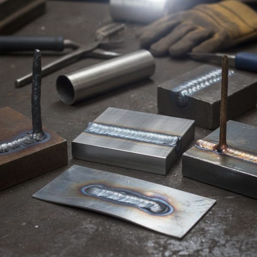
MIG weld examples range from clean, consistent stacked beads on flat mild steel joints to rougher, wider passes on vertical or overhead positions. A good MIG weld shows uniform width, consistent ripple spacing, proper fusion at the toes, and no visible porosity or undercut. Bad examples reveal problems like cold laps, burn-through, excessive spatter, or convex crowning — each pointing to a specific setting or technique issue.
What a Good MIG Weld Actually Looks Like
A properly executed MIG weld has a few visual characteristics that are hard to miss once you know what to look for.
The bead should be flat to slightly convex, not stacked high like a rope sitting on top of the metal. Width should stay consistent from start to finish — any variation suggests inconsistent travel speed or wire feed fluctuation.
The ripple pattern matters too. Tight, evenly spaced ripples indicate a steady hand and consistent settings. Irregular, scattered ripples point to arc instability or torch angle problems. Understanding what a good MIG weld looks like helps you diagnose your technique before cutting open a test piece.
Common MIG Weld Examples by Joint Type
Different joints produce different-looking welds — even when the technique is identical. Here’s what to expect from the most common configurations.
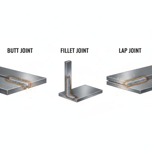
Butt Joint (Flat Position)
This is the most basic joint and usually the first one new welders practice. A good butt weld on flat mild steel looks like a slightly raised bead running perfectly centered over the gap, with fusion visible on both sides.
Underfill — where the weld sinks below the base metal surface — usually means travel speed was too fast or voltage too low. Overlap on one side suggests the torch wasn’t centered over the joint.
T-Fillet Joint
Fillet welds on a T-joint are probably the most common MIG welds in fabrication and repair work. The bead should form a roughly 45-degree triangle in cross-section, with equal legs on both pieces.
One leg consistently longer than the other is a classic sign the torch was angled too far toward one plate. Porosity at the root usually points to contamination or insufficient shielding gas coverage.
Lap Joint
Lap joints require good fusion into both the top edge of the lower plate and the face of the upper plate. A solid example looks like a smooth, flat bead that blends cleanly into both surfaces without visible cold laps or rollover.
Cold laps — where the weld metal appears to curl over without fully fusing — are common on lap joints when amperage is too low or travel speed too fast.
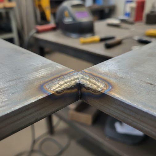
Corner Joint (Outside)
Outside corner welds on thin material can be tricky. A clean example shows a flush bead that doesn’t overflow the edges or create excessive buildup on either face. MIG welding sheet metal corner joints requires lower wire feed speed and shorter arc length to avoid burn-through.
MIG Weld Examples by Position
Position changes everything. The same machine settings that produce a beautiful flat weld may create problems the moment you tilt the work or start welding overhead.
Position
Visual Characteristics
Common Issues
Flat (1F / 1G)
Smooth, consistent ripple; controlled puddle
Easy to overload puddle; excess buildup
Horizontal (2F / 2G)
Bead tends to sag slightly to lower plate
Undercut on upper toe; overlap on lower
Vertical Up (3F / 3G)
Narrower bead with slight weaving
Cold laps; underfill; inconsistent width
Vertical Down
Faster travel; flatter bead profile
Poor penetration; porosity risk
Overhead (4F / 4G)
Tighter, smaller puddle; more difficult
Dripping; inconsistent fusion
Vertical-up welds on a T-joint are a good benchmark. Welding vertical MIG joints correctly requires a tighter arc, slightly reduced voltage, and a controlled weave or stringer bead depending on material thickness.
Examples of Bad MIG Welds — and What They Indicate
Bad welds are just as informative as good ones. Each defect is a clue.
Porosity (pitting or holes in the bead): Usually caused by contamination, moisture, or inadequate shielding gas. Can appear as surface pits or internal voids found during destructive testing.
Undercut: A groove melted into the base metal along the weld toe, leaving it thinner than the surrounding material. Typically caused by excessive voltage or incorrect torch angle.
Excessive spatter: Scattered metal balls around the weld bead. Usually points to voltage too low, wire feed too high, or incorrect gas mixture. Some spatter is normal; heavy spatter suggests a settings problem.
Cold lap / incomplete fusion: The weld metal sits on top of the base metal without truly bonding. Caused by too-fast travel speed, insufficient amperage, or contaminated base material.
Burn-through: A hole melted completely through the base metal. Common on thin material when heat input is too high or travel speed too slow.
Convex crowning (high ropey bead): The bead stands too tall and narrow. Usually a sign of insufficient voltage for the wire feed rate being used.
MIG Weld Examples by Material
The material being welded changes what a “good” weld looks like. Mild steel, stainless, and aluminum each have their own visual signatures.
Mild steel: The most forgiving. Welds appear gray-silver when cooled. Scaling or discoloration near the bead is normal but should be minimal with good gas coverage.
Stainless steel: Welds should show gold, light blue, or silver heat tint near the bead — not heavy black oxidation, which suggests inadequate shielding. MIG welding stainless steel requires tri-mix gas (typically 90% helium, 7.5% argon, 2.5% CO₂) for clean results and proper penetration.
Aluminum: Aluminum MIG welds look rougher than steel welds. The bead is typically brighter white-silver, wider, and flatter. Soot or black deposits around the bead indicate contamination or wrong gas. Pure argon is the correct shielding gas for aluminum MIG work — choosing the right gas for MIG welding aluminum directly affects bead appearance and quality.
Chromoly: Welds on chromoly look similar to mild steel but may require post-weld heat treatment depending on the application. MIG welding chromoly steel is achievable but needs careful attention to preheat requirements on thicker sections.
Reading a Cross-Section: What a Bend or Cut Test Reveals
Visual inspection only tells part of the story. Cutting through a weld and examining the cross-section — or performing a bend test — reveals internal quality.
A well-fused MIG weld cross-section shows:
– Complete root penetration into the base metal
– No visible voids, cracks, or inclusions
– A consistent fusion zone on both sides
– No porosity pockets beneath the surface
A weld that looks acceptable on the surface can still fail a bend test if penetration is shallow. This is why experienced welders run destructive tests on their first passes when setting up a new job or dialing in unfamiliar settings.
Machine Settings and Their Effect on Weld Appearance
Settings directly dictate what the bead looks like. This table gives a quick reference for how adjustments change the visual result.
Setting Adjustment
Effect on Weld Appearance
Voltage too high
Flat, wide bead; possible undercut; heavy spatter
Voltage too low
High, narrow, ropey bead; poor fusion
Wire feed too fast
Stubbing; burn-back; convex bead
Wire feed too slow
Thin bead; burn-through risk; inconsistent arc
Travel speed too fast
Narrow bead; underfill; poor fusion
Travel speed too slow
Wide, overbuilt bead; burn-through on thin material
Torch angle off
Asymmetric fusion; one-sided bead profile
For beginners, the Lincoln Electric Weld-Pak 140 HD has built-in settings guides printed on the wire feed door — a useful starting point for matching wire diameter, material thickness, and voltage settings before striking an arc.
Practical Tips for Improving Your MIG Weld Examples
– Run test beads on scrap first. Every new material, joint type, or position needs a test pass before working on real parts.
– Compare your travel angle. A 5–15 degree drag (pull) angle is typical for most MIG welding situations. Whether you push or pull a MIG welder affects bead profile and penetration depth.
– Check your gas flow rate. 15–25 CFH is standard for most indoor welding. Too low and you get porosity; too high creates turbulence that draws in air.
– Clean the base metal. Mill scale, rust, oil, and paint all cause contamination defects visible in the finished bead.
– Watch the puddle, not the arc. Experienced welders focus just behind the arc where the molten pool is forming, not directly on the tip.
FAQ
What does a MIG weld look like when it has good penetration?
Good penetration isn’t always visible from the top. On the surface, the bead should blend smoothly into the base metal at both toes without undercut or cold lap. On thinner material, slight penetration showing through the back side of a butt weld is a reliable indicator. A cross-section cut through the weld is the most reliable way to confirm root fusion on thicker sections.
Why do my MIG welds look lumpy and uneven?
Lumpy, uneven beads usually come from inconsistent travel speed or a fluctuating arc caused by incorrect wire stick-out length. Keep your contact tip-to-work distance at around 3/8 to 5/8 inch for most applications. Inconsistent hand movement is the most common cause, especially for newer welders still building muscle memory.
What should MIG welds on aluminum look like compared to steel?
Aluminum welds look noticeably different from steel. They’re typically brighter, wider, and flatter, with less defined ripple structure. A light silver-white color is normal. Black soot deposits or heavy oxidation around the bead indicate contamination issues or incorrect shielding gas — aluminum requires pure argon, not the CO₂ blends used for mild steel.
How can I tell if my MIG weld failed without cutting it open?
Surface defects like porosity, undercut, cracks, and cold lap are visible to the naked eye or with a wire brush and good lighting. A dye penetrant test can reveal surface-breaking cracks that aren’t immediately obvious. For internal defects, destructive testing (bend test or cross-section cut) is the most accessible method for shop-level evaluation without NDT equipment.
What does a MIG weld look like on exhaust pipe?
Exhaust pipe welds are typically small, tight beads on thin-wall tubing, often in awkward positions. A clean example shows full fusion around the circumference without gaps, cold laps, or burn-through. Welding exhaust pipe with a MIG welder requires lower heat settings and often a stitch or tack-and-fill technique to manage heat on thin material.
Can I judge weld quality just from the color?
Color gives useful clues but isn’t definitive. On mild steel, a clean gray bead with slight blue or gold tint at the heat-affected zone is typical. Heavy black scale suggests excessive heat or poor gas coverage. On stainless, consistent gold or blue tint is acceptable; black oxidation is not. Color alone can’t confirm internal fusion or penetration depth.
What’s the difference between a stringer bead and a weave bead in MIG welding?
A stringer bead is a straight, narrow pass with minimal side-to-side movement — it’s faster, produces less heat input, and works well for thinner material or root passes. A weave bead involves deliberate side-to-side motion to cover wider gaps or fill passes on thicker material. Weave beads generally look wider with a more pronounced ripple pattern and carry higher heat input, which can be a concern on heat-sensitive materials.
The clearest path to better MIG welds is combining visual feedback with deliberate settings adjustments. Every bad bead tells you exactly what went wrong — undercut points to voltage, porosity points to gas or contamination, cold lap points to amperage or travel speed. Train yourself to read these signals instead of just grinding them off, and your weld quality will improve faster than any other single habit.