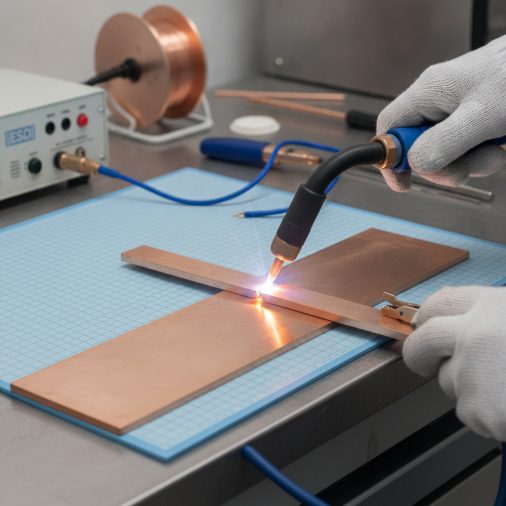
Copper’s thermal conductivity is roughly 10 times higher than mild steel, which means the heat from your TIG arc disperses almost as fast as you put it in. That single characteristic explains why welding copper frustrates so many welders — even experienced ones.
TIG welding is the preferred process for copper because it delivers precise heat control, supports helium-based shielding gas for deeper penetration, and allows exact filler rod selection for different copper alloys. ESD (electrostatic discharge) welding of copper refers to specialized joining in electronics manufacturing where controlled, contamination-free processes are critical. For structural copper work, TIG welding with ERCu or ERCuSi-A filler, preheat between 200–700°F depending on thickness, and 100% argon or argon/helium shielding gas produces reliable, high-conductivity welds.
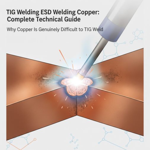
Why Copper Is Genuinely Difficult to TIG Weld
The challenges with copper aren’t about technique alone. They’re built into the material’s physics.
Copper’s thermal conductivity — approximately 226 BTU/(hr·ft·°F) — pulls heat away from the weld puddle faster than most arcs can replace it. This means the base metal never gets properly fluid unless you compensate aggressively.
The main issues welders face:
– Heat sink effect — Surrounding base metal acts as a constant cooling system, requiring higher amperage or preheat
– Oxidation sensitivity — Copper oxidizes rapidly at welding temperatures, contaminating the weld unless shielding is excellent
– Porosity — Oxygen and hydrogen absorption causes gas pockets inside the bead
– Distortion — High thermal expansion coefficient leads to warping, especially on sheet and thin plate
– Hot cracking — Certain copper alloys (especially those with bismuth or lead) are susceptible to solidification cracking
Pure copper is the hardest to weld. Copper alloys like silicon bronze, phosphor bronze, and cupronickel are more forgiving because their alloying elements reduce conductivity slightly and improve weld pool behavior.
What ESD Welding Copper Actually Means
The term “ESD welding copper” appears in two distinct contexts, and it’s worth separating them clearly.
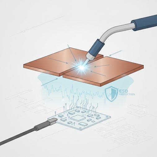
In electronics and semiconductor manufacturing, ESD refers to electrostatic discharge — the sudden current flow that can destroy sensitive components. In this context, “ESD welding copper” typically describes precision joining processes (often micro-TIG, resistance welding, or laser welding) performed in ESD-controlled environments. Technicians working on copper busbars, ground straps, or conductive assemblies near sensitive electronics must follow strict ESD handling protocols during welding operations.
In general fabrication, ESD welding copper sometimes appears as shorthand for electrostatic discharge welding — a less common variant of resistance welding used in specialized industrial applications for copper contacts and connectors.
For most readers searching this topic, the relevant application is TIG welding copper in environments or on components where ESD sensitivity matters — such as electrical panels, grounding conductors, or copper buswork adjacent to electronics.
MIG welding copper is possible in some configurations, but TIG remains the dominant choice wherever weld quality, conductivity, and contamination control are priorities.
Filler Rod Selection for TIG Welding Copper
Choosing the wrong filler is one of the most common reasons copper TIG welds fail. The filler must match the base metal’s composition while also addressing specific weld defect risks.
Filler Rod
Base Metal
Key Properties
Best Application
ERCu (Deoxidized Copper)
Pure copper, ETP copper
High conductivity, good fluidity
Electrical conductors, busbars
ERCuSi-A (Silicon Bronze)
Copper, brass, bronze
Excellent fluidity, porosity resistance
General copper fabrication, brazing overlay
ERCuSn-A (Phosphor Bronze)
Phosphor bronze, tin bronze
High strength, wear resistance
Bearing components, structural bronze
ERCuNi (Cupronickel)
Cupronickel alloys
Corrosion resistance
Marine, heat exchanger applications
ERCuAl-A2 (Aluminum Bronze)
Aluminum bronze
High strength, corrosion resistance
Heavy structural, marine hardware
For ESD-sensitive applications involving copper grounding or buswork, ERCu is typically preferred because it preserves electrical conductivity closest to the base copper. Choosing the right TIG welding filler rod impacts not just weld integrity but also the electrical performance of the finished joint.
Shielding Gas: Argon vs. Helium for Copper TIG Welding
Gas selection has a bigger impact on copper TIG welding than most people expect.
100% Argon is workable for thin copper (under 1/8 inch) and copper alloys. It’s stable, widely available, and produces a good arc at standard flow rates (15–25 CFH).
Helium or Argon/Helium Mixtures are significantly better for pure copper and heavier sections. Helium produces a hotter arc, which partially offsets copper’s aggressive heat dissipation. A common field mix is 75% helium / 25% argon, which balances arc stability with penetration.
For pure copper heavier than 3/16 inch, many experienced fabricators run pure helium at 20–30 CFH. The arc is less stable than argon, but the heat input becomes adequate for achieving full fusion without excessive preheat.
Understanding which shielding gas to use for TIG welding becomes especially important with non-ferrous metals like copper, where porosity and oxidation are constant risks.
One practical note: Helium is considerably more expensive than argon. For production work or ESD copper assembly environments, the cost difference matters across a full work week of operation.
Preheat Requirements by Copper Thickness
Preheat is non-negotiable for most copper TIG welding. Without it, the heat sink effect wins every time.
Material Thickness
Recommended Preheat
Under 1/16 inch
Often none required, use low amperage
1/16 – 1/8 inch
200–300°F
1/8 – 1/4 inch
300–500°F
1/4 – 1/2 inch
500–700°F
Over 1/2 inch
700°F+, may require sustained interpass heat
Preheat the entire workpiece or assembly, not just the joint area. Because copper conducts so well, localized preheat dissipates almost immediately once the torch moves into position.
An oxy-acetylene torch or propane rosebud works well for preheating copper. In an ESD-controlled environment, electric resistance preheating pads are preferable because they eliminate combustion gases and open flames near sensitive components.
Monitor interpass temperature carefully. Letting thick copper cool significantly between passes can cause lack of fusion at the root or cause the heat to never reach the level needed for proper flow.
TIG Welding Machine Settings for Copper
Copper typically requires higher amperage than steel of equivalent thickness due to heat loss. The general starting point is roughly 1 amp per 0.001 inch of material thickness — but copper often needs 20–40% more than that baseline.
Copper Thickness
Starting Amperage (DCEN)
Tungsten Diameter
Filler Rod Diameter
0.040 inch
40–60A
1/16 inch
1/16 inch
1/16 inch
70–100A
3/32 inch
3/32 inch
1/8 inch
120–160A
1/8 inch
1/8 inch
3/16 inch
180–250A
3/16 inch
3/16 inch
1/4 inch
250–350A+
1/4 inch
1/8–3/16 inch
Use DCEN (direct current electrode negative) for copper TIG welding. AC is not required since copper doesn’t have the oxide layer that aluminum does.
A TIG welding amperage to thickness reference chart is a useful baseline, though copper will consistently demand the higher end of any amperage range for a given thickness.
A foot pedal or fingertip amperage control is especially valuable when welding copper because you’ll need to adjust heat reactively as the workpiece heats up during the weld. TIG welding without a foot pedal is possible, but copper’s rapidly changing thermal state makes manual amperage control much harder to manage precisely.
Tungsten Electrode Selection for Copper TIG Welding
For DCEN copper TIG welding, use a 2% thoriated (red band), 2% ceriated (gray band), or lanthanated tungsten electrode. These hold a sharpened point well under the high amperage demands of copper welding.
– 2% Thoriated (WT20) — Long-established standard for DCEN work; handles high amperage without balling
– 2% Ceriated (WC20) — Good low-amperage starts, handles mid-range copper work effectively
– 2% Lanthanated (WL20) — Versatile replacement for thoriated with similar performance and no radioactivity concerns
Sharpen the tungsten to a tight point. A wider taper with a small flat tip works well for higher amperage copper work, providing arc stability at the currents copper demands.
Selecting the correct tungsten for TIG welding affects arc stability, electrode longevity, and ultimately weld quality — all of which matter more on copper than they do on steel.
Common Problems When TIG Welding Copper
Porosity
The most frequent defect in copper TIG welds. Usually caused by moisture, oil contamination, or inadequate shielding gas coverage. Always clean copper aggressively before welding — acetone wipe followed by mechanical cleaning. Removing heavy oxidation from copper before welding is not just cosmetic; oxide contamination directly causes porosity.
Lack of Fusion
Happens when preheat is insufficient or amperage is too low for the section thickness. The bead appears to sit on top of the base metal rather than fusing into it. Increase preheat, switch to a helium-based gas mix, and bump amperage up.
Cracking
More common in free-machining copper alloys that contain lead or bismuth. These elements form low-melting-point phases at grain boundaries that crack under solidification stress. When welding these alloys is unavoidable, use a compatible low-dilution filler and preheat carefully.
Burn-Through on Thin Copper
On sheet copper under 1/16 inch, excessive amperage destroys the joint instantly. Use a backing bar (copper backing bar for copper work), reduce amperage to the minimum that still achieves fusion, and keep travel speed high.
Arc Instability or Spitting
Often a gas coverage or contamination issue on copper. Arc spitting during TIG welding frequently traces back to surface contamination, a damaged gas lens, or improper gas flow — all of which are more impactful on non-ferrous metals.
When TIG welding copper components in ESD-sensitive environments — electrical assemblies, grounding conductors, or copper buswork near circuit boards — several additional precautions apply beyond standard copper welding procedure.
– Ground the workpiece properly to the welding table, not to nearby sensitive electronics
– Use ESD-safe work surfaces and handling equipment during fixturing and post-weld inspection
– Avoid compressed air blowdown near electronics during cleaning operations
– Maintain low-humidity environments when possible, since moisture both promotes oxidation and increases ESD risk
– Keep power cables away from signal cable paths to prevent inductive interference during the welding arc
In precision electronics manufacturing, resistance welding or laser welding often replaces TIG for micro-scale copper joints because they offer better repeatability and smaller heat-affected zones. But for grounding conductors, bus bars, and structural copper work adjacent to electronics, TIG remains the practical production choice.
FAQ
What filler rod should I use to TIG weld pure copper?
ERCu (deoxidized copper) is the standard filler rod for TIG welding pure copper. It closely matches the base metal’s conductivity and composition while providing enough deoxidizers to reduce porosity risk. For copper that will carry electrical current — busbars, grounding conductors — ERCu preserves conductivity better than silicon bronze alternatives. Always clean the filler rod with acetone before welding to remove any surface oils.
Do I need to preheat copper before TIG welding?
Yes, in most cases. Copper’s thermal conductivity is so high that the arc heat dissipates before the weld pool reaches proper fusion temperature without preheat. For material 1/8 inch and thicker, preheat to at least 300–500°F. Thin copper under 1/16 inch may not require preheat, but higher amperage and fast travel speed are still necessary to achieve proper fusion.
Can you TIG weld copper to steel?
TIG welding copper directly to steel is difficult and generally produces poor results due to metallurgical incompatibility and the massive difference in thermal expansion. Silicon bronze filler (ERCuSi-A) is often used to braze-weld copper to steel using TIG, where the filler bonds to both surfaces without fully alloying with the steel. This is a common technique in artistic metalwork and some repair applications.
What causes porosity in copper TIG welds and how do I fix it?
Porosity in copper TIG welds is almost always caused by one of three things: surface contamination (oil, oxide, or moisture), inadequate shielding gas coverage, or hydrogen pickup from the base metal or atmosphere. Fix it by cleaning copper aggressively before welding, increasing gas flow rate (especially with argon), and ensuring the gas lens and cup are in good condition. Switching from standard argon to an argon/helium mix also helps by keeping the puddle fluid longer, allowing gas to escape before solidification.
What amperage do I need to TIG weld 1/4-inch copper?
Quarter-inch pure copper typically requires 250–350+ amps with appropriate preheat. This is significantly higher than what you’d use on 1/4-inch steel because of copper’s heat sink effect. Preheat the piece to 500–700°F before welding, use helium or an argon/helium mix, and use a large enough tungsten (3/16 or 1/4 inch diameter) to handle the amperage without rapid erosion.
Is TIG or MIG welding better for copper electrical busbars?
TIG welding is generally better for copper busbars because it offers cleaner welds with less spatter, better control over heat input, and produces joints with higher electrical conductivity. MIG welding copper busbars is possible but typically results in more spatter contamination and less precise fusion at joints. For high-current applications where joint resistance matters, TIG with ERCu filler is the standard approach.
What does ESD-safe TIG welding of copper involve?
ESD-safe TIG welding of copper means performing the weld while following electrostatic discharge precautions to protect nearby sensitive electronics or components. This includes proper workpiece grounding isolated from electronics, ESD-safe handling equipment, low-humidity work environments, and keeping power cables away from signal lines. In some facilities, technicians wear ESD wrist straps and work on grounded conductive mats even during welding operations when the assembly contains ESD-sensitive devices.
Copper rewards patience and preparation more than any other common weld metal. Get the preheat right, match your filler to the alloy, and push toward helium-based shielding on anything heavier than 1/8 inch. In ESD-sensitive environments, those fundamentals still apply — they’re just layered on top of additional handling protocols that protect the surrounding assembly. The weld itself is still a TIG weld; the ESD context changes how you handle the work, not how you run the arc.