
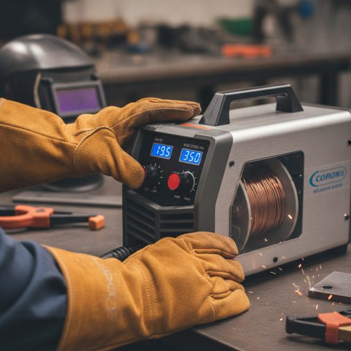
You’ve loaded flux core wire, set your polarity, and you’re ready to weld — but the machine has voltage and wire-feed speed knobs with no clear flux core starting point. Getting the heat dialed in correctly makes the difference between a solid bead and burn-through, porosity, or poor fusion.
Flux core heat settings depend on material thickness, wire diameter, machine type, and welding position. Voltage controls arc length and bead profile, while wire-feed speed (WFS) controls amperage and heat input. For most self-shielded flux core wire on mild steel, voltage typically ranges from around 14V to 22V and WFS from roughly 150 to 400 inches per minute — but always start with your machine’s chart or wire manufacturer’s data and adjust from there.
How Flux Core Heat Works Differently Than Solid Wire MIG
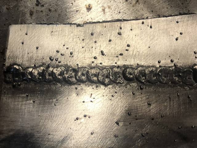
In standard MIG welding with solid wire and shielding gas, voltage and WFS work together much the same way. Flux core follows the same electrical principle, but the wire burns hotter for a given diameter because the flux core increases overall resistance slightly.
Self-shielded flux core (FCAW-S) and gas-shielded flux core (FCAW-G) also behave differently from each other. Self-shielded wire generates its own shielding from the flux chemistry and generally runs at higher heat to drive off contaminants. Gas-shielded flux core runs cleaner and is more sensitive to voltage changes.
For the most common home and small-shop scenario — a 120V or 230V machine running self-shielded flux core wire — you are adjusting two variables: voltage (sometimes shown as a tap or numbered setting) and wire-feed speed. Understanding how each one affects the weld helps you troubleshoot faster than memorizing a single chart.
Voltage: What It Controls and How to Adjust It
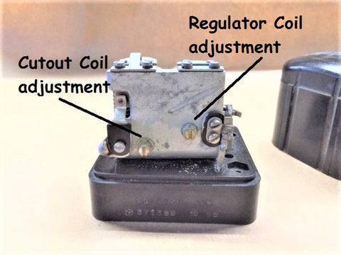
Voltage sets the arc length and bead width. Higher voltage produces a flatter, wider bead with more fluidity in the puddle. Lower voltage narrows the arc and increases convexity (a taller, narrower bead).
Too much voltage causes the arc to become erratic, spatter to increase, and the bead to flatten out excessively. Too little voltage produces a tight, stubbing arc where the wire digs into the base metal without establishing a smooth puddle.
On machines with discrete voltage taps (common on entry-level 120V welders), you may have two to four positions rather than a continuously variable dial. In those cases, choose the tap closest to your target and fine-tune heat by adjusting wire-feed speed.
Wire-Feed Speed: The Primary Heat Variable
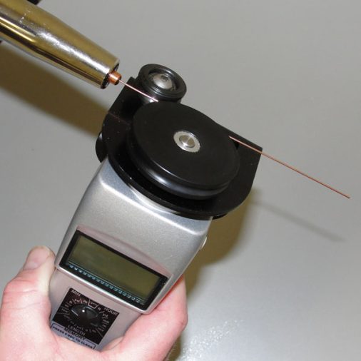
Wire-feed speed controls how much wire enters the arc per minute, and that directly controls amperage and heat input. Increasing WFS raises amperage, deepens penetration, and adds more filler. Decreasing WFS reduces heat and slows deposition.
When WFS is too high for the selected voltage, the wire burns back slowly and produces a stubby, popping arc with excessive spatter. When WFS is too low, the wire burns back to the contact tip or the arc becomes inconsistent and hard to control.
A smooth, consistent hissing or crackling sound — often described as bacon frying — generally indicates the arc is reasonably balanced. A loud popping or sputtering sound usually points to a voltage or WFS mismatch. You can find a more detailed breakdown in this flux core MIG welding settings chart and practical guide.
General Starting Settings by Material Thickness

The table below provides general starting-point guidance for self-shielded flux core wire on mild steel. These are not specification values. Actual settings will vary by machine brand, wire classification, wire diameter, joint type, and position. Always check your wire manufacturer’s published data and your machine’s recommended settings chart first.
| Material Thickness | Wire Diameter | Voltage (Approx.) | WFS Starting Range | Notes |
|---|---|---|---|---|
| 18–16 gauge (thin sheet) | 0.030 in | 14–16V | 150–220 IPM | Use stitch or tack technique; burn-through risk is high |
| 3/16 in (approx. 4.8 mm) | 0.030–0.035 in | 17–19V | 220–300 IPM | Common structural repair range on 120V machines |
| 1/4 in (approx. 6.4 mm) | 0.035 in | 18–21V | 280–370 IPM | May require multiple passes; 230V machine preferred |
| 3/8 in (approx. 9.5 mm) | 0.035–0.045 in | 20–23V | 330–420 IPM | Multiple passes required; 230V or higher machine needed |
Thicker material beyond 1/4 inch on a 120V machine typically requires multiple passes and careful interpass temperature management. A 230V machine gives you more range and better duty cycle for sustained heat input on heavier plate.
Polarity Matters for Flux Core
Self-shielded flux core wire almost always runs on DC electrode negative (DCEN), also called straight polarity. This is the opposite of solid wire MIG, which uses DC electrode positive (DCEP). Running self-shielded flux core on the wrong polarity produces a rough, spattered, poorly fused weld regardless of how well your voltage and WFS are set.
Gas-shielded flux core wire (FCAW-G) typically runs on DCEP. Always confirm the polarity requirement on your wire’s data sheet or spool label before adjusting heat settings — incorrect polarity will make any setting combination perform poorly.
If you are unsure how polarity interacts with your process, the detailed explanation of DCEP versus DCEN in MIG and flux core welding covers the difference clearly.
Travel Speed and Its Effect on Heat Input
Travel speed is a heat variable that welders sometimes overlook when focused entirely on voltage and WFS. Moving too slowly concentrates heat, widens the bead, risks burn-through on thin metal, and can cause excessive slag inclusion on flux core. Moving too quickly produces a narrow, convex bead with poor fusion at the toes.
A consistent travel speed around 6–12 inches per minute is a rough starting range for flat-position flux core on mild steel, but the correct speed depends on what the puddle is telling you. The puddle should be fluid but controlled, with slag flowing behind it rather than getting trapped under the arc.
Welding Position and Heat Adjustment
Flat and horizontal positions allow the highest heat input because gravity helps control the puddle. Vertical and overhead positions require lower heat — typically reducing voltage by one step or reducing WFS — to prevent the puddle from running or sagging before it solidifies.
For vertical-up welding with flux core, a slight weave or upside-down V motion helps control puddle flow while maintaining fusion at the edges. Vertical-down is generally limited to thin material and low heat settings because the arc tends to push the puddle ahead of the weld, risking cold laps and poor fusion on thicker plate.
Common Heat-Related Defects and How to Correct Them
Burn-Through on Thin Metal
Burn-through on thin gauge steel almost always means heat is too high for the thickness. Reduce voltage one step, reduce WFS slightly, and increase travel speed. Using a stitch technique — short welds with cooling time between them — also reduces heat buildup on sheet metal. For detailed technique guidance, the article on welding thin metal with flux core covers this scenario specifically.
Lack of Fusion or Cold Laps
A bead that sits on top of the base metal rather than fusing into it usually means heat is too low, travel speed is too fast, or the work angle is incorrect. Increase voltage slightly, reduce travel speed, and make sure the gun angle keeps the arc directed into the joint rather than at the trailing puddle.
Excessive Spatter
Heavy spatter is common with flux core and increases with voltage imbalance, contaminated base metal, incorrect polarity, or wire feed inconsistency. If spatter is excessive despite correct polarity and clean base metal, try a small voltage increase while keeping WFS constant, and check that the contact tip is not worn or clogged.
Porosity
Porosity in flux core welds often traces back to contaminated base metal (rust, oil, paint, or mill scale), a damaged or wet wire spool, or incorrect technique rather than heat settings alone. Some porosity in FCAW-S welds on moderately rusted steel is normal. Excessive porosity on clean, prepared material may indicate the wire has absorbed moisture — store wire in a sealed container when not in use.
Practical Tips for Dialing In Heat Settings
- Always start with your machine’s built-in settings chart or the wire manufacturer’s published data before making adjustments.
- Run a test bead on scrap of the same thickness and joint type before welding the actual piece.
- Listen to the arc — a smooth, consistent sound is one of the fastest indicators of balanced settings.
- On tap-style machines, if the arc sounds right but heat still feels slightly off, adjust WFS in small increments of 10–20 IPM.
- Check bead profile after each test pass: a flat bead with smooth toe wash-in generally indicates good fusion and appropriate heat.
- Allow the workpiece to cool between passes on thicker material to avoid excessive heat buildup and distortion.
- Clean slag between every pass with a chipping hammer and wire brush before running the next bead.
For a reference-style breakdown of amperage ranges by wire size and thickness, the flux core welding amperage chart provides a useful quick-reference starting point.
Safety Considerations for Flux Core Heat Levels
Higher heat settings produce more intense UV radiation, more spatter, and significantly more fume. Flux core wire generates more fume than solid MIG wire even at equivalent heat levels, so ventilation is especially important. Work in a well-ventilated space, use local fume extraction when possible, and wear a properly rated welding respirator when ventilation is limited.
Wear a welding helmet with a lens shade appropriate for the amperage being used — shade 10 is a common starting point for flux core at typical amperages, but check the lens manufacturer’s guidance for your specific heat range. Auto-darkening helmets with adjustable shade ranges simplify this when moving between heat settings.
Keep spatter in mind when welding at higher heat. Clear flammable materials from the work area, cover surfaces that cannot be moved, and have a fire extinguisher accessible. Allow all workpieces to cool fully before handling — high heat settings on thick plate can retain significant temperature well after the arc stops.
The health implications of welding fume exposure are worth understanding separately. The article on MIG and flux core welding health risks explains the primary fume and radiation hazards in plain language.
When to Use a Settings Chart vs. a Welding Procedure
For general repair, hobby fabrication, and non-structural work, a machine chart combined with test passes on scrap is a practical and sufficient approach to dialing in heat. You adjust by feel, sound, and visual inspection of the bead.
For structural work, load-bearing fabrication, pressure-containing components, or any job covered by a code or standard, you need a qualified welding procedure specification (WPS) that defines approved settings tested to meet the requirements. Bead appearance alone does not confirm structural integrity, and settings that look correct visually may not meet mechanical property requirements without procedure qualification and testing.
Frequently Asked Questions
What voltage should I use for flux core welding on 1/4-inch steel?
For 0.035-inch self-shielded flux core wire on 1/4-inch mild steel, a voltage in the range of approximately 18–21V is a commonly used starting point, paired with wire-feed speeds in the 280–370 IPM range. Confirm against your wire manufacturer’s data and your machine’s chart, and run test passes on scrap before committing to the actual joint. A 230V machine handles this thickness more comfortably than a 120V machine.
Why does my flux core weld have too much spatter even with correct settings?
Excessive spatter despite correct voltage and WFS often points to incorrect polarity (check that self-shielded wire is on DCEN), a worn or clogged contact tip, contaminated base metal, or moisture-damaged wire. A slight voltage increase can sometimes reduce spatter on FCAW-S wire, but polarity and wire condition should be checked first. Spatter is inherently higher with self-shielded wire than with gas-shielded processes.
Can I use flux core settings designed for 0.035-inch wire with 0.030-inch wire?
No — wire diameter directly affects amperage output at a given wire-feed speed. Thinner wire (0.030 in) burns faster and produces more amperage per IPM than thicker wire (0.035 in) at the same speed. Using 0.035-inch settings with 0.030-inch wire will result in significantly too much heat. Always match your WFS and voltage starting points to the specific wire diameter you are running.
How do I know if my flux core heat setting is too low?
Signs of insufficient heat include a convex, ropey bead that sits proud of the base metal rather than washing smoothly into the toes, lack of fusion visible at the edges of the weld, a popping or stubbing arc, and cold laps where the bead overlaps but does not fuse. Increase voltage slightly and reduce travel speed as a first adjustment, then reassess on a test piece.
Does welding position change the heat settings I should use for flux core?
Yes. Flat and horizontal positions support higher heat because gravity assists puddle control. Overhead and vertical positions generally require lower voltage or reduced WFS to prevent the puddle from running or sagging. A typical adjustment when moving from flat to vertical is to reduce voltage by one step or reduce WFS by roughly 10–15 percent, then fine-tune based on puddle behavior during test passes.
Is flux core welding on thin sheet metal manageable with heat settings alone?
Heat settings help, but technique matters just as much on thin material. Even at low settings, self-shielded flux core concentrates significant heat. Stitch welding, tacking in sequence to distribute heat, and allowing cooling time between passes are all necessary alongside lower voltage and WFS settings. For automotive sheet metal specifically, the risks and techniques involved in welding body panels with flux core are worth reviewing before starting.
Start With the Chart, Finish With the Test Bead
No single setting works across all machines, wire classifications, thicknesses, and positions. The most reliable approach is to begin with your machine’s published chart or your wire manufacturer’s data, set polarity correctly, and run test passes on matching scrap before welding the actual workpiece. Adjust voltage and wire-feed speed in small steps while listening to the arc and inspecting the bead profile. For structural or regulated applications, always work from a qualified welding procedure rather than relying on trial-and-error settings alone.


