
Use this independent welding parameter estimator to plan your MIG or Stick welding setup before you strike an arc. Enter your base metal thickness, wire or electrode diameter, and process type to instantly calculate recommended amperage range, wire feed speed, duty cycle load, and shielding gas flow rate. Results are planning estimates based on widely accepted welding engineering guidelines and should always be verified against your specific machine manual and a test weld on scrap material before production use.
Miller Welding Calculator: Amperage, Duty Cycle & Wire Feed Speed Estimator
An independent planning estimator for MIG and Stick welding parameters including recommended amperage, wire feed speed, duty cycle load, shielding gas flow rate, heat input, and electrode burn-off rate based on material thickness and process type.
How to Use This Calculator
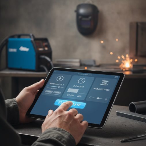
Follow these steps to get accurate planning estimates from the calculator:
- Select your welding process — choose MIG (GMAW) for wire-feed welding or Stick (SMAW) for electrode welding. Wire feed speed results apply to MIG only.
- Enter base metal thickness — type the actual measured thickness of your workpiece in inches. Common values are 0.063 in (16 gauge), 0.125 in (1/8 in), and 0.250 in (1/4 in).
- Select wire or electrode diameter — pick the consumable size you plan to use. Thinner wire suits thinner metal; heavier electrodes carry more current for thick sections.
- Choose joint position — flat and horizontal positions allow full amperage; vertical and overhead require reduced amperage to control the weld pool.
- Select base metal type — mild steel, stainless, or aluminum each require a correction factor due to differences in thermal conductivity and melting point.
- Enter your machine’s rated output and duty cycle — these values appear on the machine nameplate or in the operator manual and are needed to calculate available duty cycle at your operating amperage.
- Select shielding gas cup size — match the cup size to your MIG gun nozzle diameter for an accurate gas flow estimate.
- Enter estimated travel speed — your typical travel speed in inches per minute is used to calculate relative heat input per inch of weld.
- Read the results — all six output values update instantly. Use them as a starting point, then fine-tune on scrap material.
Understanding the Calculator Inputs
Welding Process: Select MIG (GMAW) if you are using a wire-feed machine with a shielding gas supply, or Stick (SMAW) if you are using coated electrodes. This selection controls which formula set is most meaningful. Wire feed speed results are only valid when MIG is selected; the burn-off rate result is most relevant for Stick planning.
Base Metal Thickness: Measure the actual thickness of the thinnest piece in your joint using calipers or a sheet metal gauge. Enter the value in decimal inches — for example, 1/8 inch is 0.125, 3/16 inch is 0.1875, and 1/4 inch is 0.250. The amperage rule of approximately 1 amp per 0.001 inch of thickness is the most widely cited starting point in welding engineering references and machine manufacturer charts. Accuracy here directly affects every other output.
Wire / Electrode Diameter: Choose the consumable size you intend to use. For MIG welding, 0.023 in wire is suited to sheet metal under 18 gauge, 0.030 in covers light gauge up to about 3/16 in, 0.035 in is the most common general-purpose choice, and 0.045 in is used for heavier structural work. For Stick, 3/32 in electrodes (such as 6013 or 7018) are standard for thinner plate, 1/8 in is the workhorse size for most structural applications, and 5/32 in is used for heavy sections requiring higher deposition. Electrode diameter sets the current-carrying capacity and directly influences the wire feed speed calculation.
Joint / Position Factor: Flat and horizontal positions allow the full calculated amperage because gravity assists puddle control. Vertical welding requires roughly a 10% reduction to prevent the puddle from sagging, and overhead welding requires approximately a 15% reduction. These factors are applied as multipliers on the base amperage. If you are welding in multiple positions on the same joint, use the most restrictive factor.
Base Metal Type: Mild steel uses a factor of 1.00 as the baseline. Stainless steel has lower thermal conductivity and retains heat more readily, so a 5% reduction (factor 0.95) is applied to avoid overheating and sensitization of the heat-affected zone. Aluminum has higher thermal conductivity and requires more heat to establish fusion, so a 10% increase (factor 1.10) is applied. Note that aluminum MIG welding often requires a spool gun or push-pull system not captured by these simplified estimates.
Machine Rated Output and Duty Cycle: These two values appear together on your machine’s nameplate — for example, 200 A at 60% duty cycle. Enter both values accurately. The calculator uses them to determine how much of the ten-minute duty cycle period your machine can weld continuously at the recommended operating amperage without triggering thermal protection.
Shielding Gas Cup Size: Select the cup size that matches your MIG gun nozzle. Smaller cups work for tight access joints but provide less coverage; larger cups are used for higher-amperage applications and wider weld pools. This selection sets the baseline flow rate that is then adjusted for material thickness.
Estimated Travel Speed: Enter your typical travel speed in inches per minute. A comfortable manual MIG travel speed is roughly 10–20 in/min for most structural welds; faster travel reduces heat input and is used on thin material to prevent burn-through. This value feeds the relative heat input calculation and helps you compare passes or plan for distortion control.
Understanding Your Results
Recommended Amperage: This is your primary machine setting starting point, expressed in amps. It is calculated from material thickness using the 1-amp-per-0.001-inch rule, then adjusted for position and material type. Set your machine to this value on scrap material first and adjust in 5–10 amp increments based on bead appearance — a flat, smooth bead with good tie-in indicates correct amperage, while a convex ropy bead suggests too little and excessive spatter or undercut suggests too much.
Wire Feed Speed (MIG only): This result is valid only when MIG process is selected. It gives you an estimated wire feed speed in inches per minute to pair with your amperage setting. On most MIG machines, amperage and wire feed speed are directly linked — increasing wire feed speed increases amperage. Use this value as your dial starting point, then fine-tune until the arc sounds like a steady frying bacon sound with minimal spatter. For a detailed voltage and wire speed reference, see the Miller welding voltage and wire speed chart.
Available Duty Cycle at Operating Amps: This percentage tells you how many minutes out of every ten-minute period your machine can weld at the recommended amperage. A result of 80% means you can weld for 8 minutes and must rest the machine for 2 minutes. If the operating amperage is lower than the rated amperage, the available duty cycle increases because the machine runs cooler. Values are capped at 100%. If your result is below 30%, consider a machine with a higher rated output for your application.
Shielding Gas Flow Rate: This is the recommended flow rate in cubic feet per hour (CFH) at the regulator. Set your flow meter to this value before welding and verify it at the gun nozzle with a flow meter if possible. Insufficient flow causes porosity; excessive flow causes turbulence that draws atmospheric contamination into the weld pool. Outdoor or drafty conditions require higher flow rates or wind shielding.
Heat Input per Inch (Relative): This relative index in joules per inch helps you compare the thermal load of different parameter combinations. Lower heat input reduces distortion and HAZ width on thin material; higher heat input improves fusion on thick sections. Use this number to compare two setups — for example, slowing travel speed on thick plate versus increasing amperage — and choose the combination that balances fusion with distortion risk. This is a relative index, not an absolute joules-per-inch value, because voltage is embedded in the amperage estimate rather than measured directly.
Electrode Burn-Off Rate (Stick estimate): This result estimates how quickly a Stick electrode is consumed in inches per minute at the recommended amperage. Use it to estimate how many rods you will need for a job and how long each rod will last. A 14-inch rod at 2.5 in/min burn-off rate will last approximately 5.6 minutes of arc time. Multiply by the number of passes and total weld length to estimate total rod consumption. For more detail on rod quantities, the 3/32 welding rods per pound guide provides useful reference data.
Calculation Formulas Explained
Recommended Amperage Formula: The base amperage is calculated as material thickness in thousandths of an inch multiplied by 1 amp per thousandth. This gives the raw amperage for flat-position mild steel. The result is then multiplied by the joint position factor (1.00, 0.90, or 0.85) and the material type factor (1.00, 0.95, or 1.10) to produce the adjusted recommended amperage. The formula is: (thickness_in_inches × 1000) × position_factor × material_factor.
Wire Feed Speed Formula: Wire feed speed is estimated using an empirical linear relationship between amperage and wire feed speed for a given electrode diameter. The relationship takes the form: WFS = (133.33 × wire_diameter_in + 2.08) × (amperage / (wire_diameter_in × 1000)). This approximation is most accurate for ER70S-6 solid wire in the 0.023–0.045 in diameter range. The process multiplier (value 1 for MIG, value 2 for Stick) is included in the formula structure; treat wire feed speed results as valid only when MIG is selected.
Available Duty Cycle Formula: Duty cycle scales with the inverse square of the amperage ratio, a standard approximation used in welding engineering: DC_available = DC_rated × (rated_amps / operating_amps)². If operating amperage is lower than rated amperage, the ratio is greater than 1 and duty cycle increases. The result is capped at 100% using the min() function because no machine can exceed 100% duty cycle regardless of how low the operating amperage is.
Shielding Gas Flow Rate Formula: The baseline flow rate from the cup size selection is adjusted upward as material thickness increases above the 0.125 in reference point: flow = base_CFH × (1 + (thickness_in – 0.125) × 0.8). The factor 0.8 represents an 80% increase in flow per additional inch of thickness, which accounts for the larger weld pool and longer arc time at higher amperages. For thicknesses below 0.125 in, the formula reduces flow proportionally.
Heat Input Formula: Relative heat input per inch is calculated as: HI = (amperage × 60) / travel_speed_in_per_min. This is proportional to the standard heat input formula (amps × volts × 60 / travel speed) with voltage treated as a constant embedded in the amperage estimate. The result is a relative index useful for comparing setups rather than an absolute joules-per-inch measurement.
Electrode Burn-Off Rate Formula: Stick electrode burn-off rate is estimated using the empirical constant of approximately 0.0035 inches of electrode consumed per amp per minute: burn_off = amperage × 0.0035. This constant is derived from published deposition rate data for common mild steel electrodes such as E6013 and E7018 and is suitable for job planning and rod consumption estimates.
Worked Example
Scenario: You need to weld a flat butt joint on 1/4 inch (0.250 in) mild steel plate using MIG with 0.035 in ER70S-6 wire. Your machine is rated at 200 A at 60% duty cycle. You are using a standard cup and plan to travel at 12 in/min.
- Process: MIG (GMAW) — value 1
- Material thickness: 0.250 in
- Wire diameter: 0.035 in
- Position factor: Flat / Horizontal — 1.00
- Material factor: Mild Steel — 1.00
- Machine rated amps: 200 A
- Machine duty cycle: 60%
- Gas cup: Standard — 20 CFH base
- Travel speed: 12 in/min
Recommended Amperage: (0.250 × 1000) × 1.00 × 1.00 = 250 A. This exceeds the machine’s 200 A rated output, which is an important planning signal — this machine may be undersized for single-pass welding on 1/4 inch plate at full amperage.
Wire Feed Speed: (133.33 × 0.035 + 2.08) × (250 / (0.035 × 1000)) = (4.667 + 2.08) × (250 / 35) = 6.747 × 7.143 ≈ 482 in/min. This is a high wire feed speed consistent with spray transfer territory; verify your machine and gas mix support spray transfer before attempting this setting.
Available Duty Cycle: 60 × (200 / 250)² = 60 × 0.64 = 38.4%. At 250 A your 200 A machine is running above its rated output, so the available duty cycle drops below the nameplate rating. In practice the machine’s thermal protection will likely trip before reaching 250 A continuously. This confirms the machine is undersized for this application at full amperage.
Shielding Gas Flow Rate: 20 × (1 + (0.250 − 0.125) × 0.8) = 20 × (1 + 0.100) = 20 × 1.10 = 22 CFH. Set your regulator to 22 CFH for adequate pool coverage on 1/4 inch plate.
Heat Input per Inch: (250 × 60) / 12 = 15,000 / 12 = 1,250 J/in (relative). This is a high heat input value; expect some distortion on longer welds and plan for backstep or skip welding sequences to manage it.
Electrode Burn-Off Rate: 250 × 0.0035 = 0.875 in/min (Stick reference only; not applicable for this MIG example).
Interpretation: The results clearly indicate that a 200 A machine is marginal for 1/4 inch mild steel in a single pass. A practical solution is to run two passes at 180–190 A, which keeps the machine within its rated output and available duty cycle, or to use a machine rated at 250 A or higher. For vertical welding on the same joint, apply the 0.90 position factor, which reduces the recommended amperage to 225 A — still above the 200 A machine’s rating but closer to manageable with multi-pass technique.
How to Interpret the Results
When reading your results, start with the Recommended Amperage and compare it to your machine’s rated output. If the recommended amperage exceeds your machine’s rating, you have three options: use a more capable machine, reduce to multi-pass welding at a lower amperage, or accept that the single-pass result is a planning target requiring a larger machine. If the recommended amperage is well below your machine’s rating, the Available Duty Cycle result will be high, meaning you can weld for longer continuous periods without overheating the machine.
The Wire Feed Speed result for MIG should be cross-referenced against your machine’s wire feed speed range printed on the inside panel or in the manual. Most hobbyist MIG machines top out at 300–400 in/min; industrial machines reach 700 in/min or more. If the calculated wire feed speed exceeds your machine’s range, the wire diameter or amperage is too high for that machine. For additional voltage and wire speed reference data, the Miller MIG voltage and wire speed chart provides tabulated values for common setups.
The Heat Input per Inch index is most useful as a comparative tool. If you are welding thin material and concerned about warping, lower this number by increasing travel speed or reducing amperage. If you are welding thick material and concerned about lack of fusion, increase it by slowing travel speed or increasing amperage. For practical techniques on avoiding burn-through on thin plate, the guide to welding thin plate without holes covers complementary technique adjustments.
The Electrode Burn-Off Rate is most useful for Stick welding job planning. Multiply the burn-off rate by the total arc-on time for your job to estimate total electrode length consumed, then convert to rod count based on your electrode length (typically 14 inches for standard Stick electrodes). Add 10–15% for stub loss and restarts.
Common Mistakes to Avoid
- Using plate thickness instead of the thinnest member: When joining two pieces of different thickness, always base your amperage on the thinner piece to avoid burning through it. The thicker piece will still achieve fusion if technique is correct.
- Ignoring the position factor: Many welders use flat-position settings for vertical or overhead work and then wonder why the puddle sags or drips. Always apply the position reduction before setting your machine.
- Confusing machine rated amps with maximum output: The rated amperage on the nameplate is the amperage at which the duty cycle percentage is measured, not necessarily the machine’s absolute maximum. Some machines can exceed their rated amperage for short periods, but duty cycle drops sharply.
- Setting gas flow too high: More shielding gas is not always better. Excessive flow above about 35 CFH creates turbulence at the nozzle that draws atmospheric oxygen and nitrogen into the weld pool, causing porosity. Stay within the recommended range and ensure the nozzle is clean and properly seated. The MIG tip and shroud setup guide covers nozzle maintenance in detail.
- Not accounting for material type on stainless: Stainless steel retains heat much more than mild steel. Running mild steel amperage settings on stainless causes overheating, carbide precipitation in the HAZ, and distortion. Always apply the 0.95 material factor and consider reducing travel speed rather than increasing amperage.
- Treating wire feed speed and amperage as independent: On a MIG machine, wire feed speed and amperage are directly coupled — the wire feed speed determines how much current the arc draws. Changing one changes the other. Do not set amperage on the machine and then independently set wire feed speed without understanding this relationship.
- Skipping the test weld: Calculator outputs are starting points, not final settings. Material surface condition, joint fit-up, shielding gas mix, contact tip condition, and operator technique all affect the actual weld. Always run a test bead on scrap of the same material and thickness before production welding.
Limitations and Important Notes
This calculator is an independent planning tool and is not affiliated with, endorsed by, sponsored by, or representative of Miller Electric Mfg. LLC or its parent company Illinois Tool Works Inc. All results are estimates based on widely published welding engineering rules of thumb and empirical approximations.
The amperage rule of 1 amp per 0.001 inch is a starting-point guideline, not a precise engineering specification. Actual optimal amperage depends on joint design, fit-up gap, base metal surface condition, shielding gas composition, electrode classification, and operator technique — none of which are captured by this simplified model.
The wire feed speed formula uses a linear empirical approximation most accurate for ER70S-6 solid wire in the 0.023–0.045 in diameter range in short-circuit or globular transfer modes. Spray transfer, pulse MIG, and flux-cored wire processes follow different relationships and may produce significantly different results.
The duty cycle interpolation uses the inverse-square law, which is a standard approximation. Actual machine duty cycle curves are non-linear and vary by manufacturer and model. Always consult your machine’s operator manual for the actual duty cycle curve before planning extended welding operations.
Shielding gas flow adjustments assume standard indoor conditions with no significant air movement. Outdoor welding, fans, HVAC drafts, or open bay doors require substantially higher flow rates or physical wind shielding and are not modeled here.
The heat input result is a relative index only. It does not represent absolute joules per inch because voltage is not measured directly — it is embedded in the amperage estimate using an assumed voltage. For code-compliant heat input calculations on structural or pressure vessel work, measure actual voltage and amperage with calibrated instruments and use the full formula: HI = (amps × volts × 60) / travel_speed.
Material thickness is limited to 0.030–1.000 inch. Values outside this range may produce unreliable estimates. Aluminum welding parameters may require pulse MIG or spool gun setups not captured by these formulas. Always perform a test weld on scrap material and consult your machine’s operator manual before production welding.
Frequently Asked Questions
What amperage do I need to weld 1/4 inch steel?
For 1/4 inch (0.250 in) mild steel in the flat position, the standard rule of thumb gives approximately 250 amps as a starting point — calculated as 0.250 × 1000 = 250 amps. In practice, many welders achieve good fusion on 1/4 inch plate with 200–230 amps using multiple passes or by slowing travel speed to increase heat input per inch. If your machine is rated below 250 amps, plan for a two-pass weld rather than attempting a single pass at the machine’s thermal limit. Always verify with a test weld on scrap 1/4 inch plate before committing to production joints. For vertical welding on 1/4 inch plate, apply the 0.90 position factor to get a starting point of approximately 225 amps, and consider a downhill progression for thinner sections or uphill for full-penetration structural welds. The MIG vertical welding settings guide for 1/4 inch plate covers technique adjustments in detail.
How do I calculate wire feed speed for MIG welding?
Wire feed speed for MIG welding is estimated from the relationship between amperage and electrode diameter. A common empirical approach uses the formula: WFS (in/min) = (133.33 × wire_diameter_in + 2.08) × (amperage / (wire_diameter_in × 1000)). For example, with 0.035 in wire at 150 amps: WFS = (133.33 × 0.035 + 2.08) × (150 / 35) = 6.747 × 4.286 ≈ 289 in/min. On most MIG machines, wire feed speed and amperage are directly coupled — the wire feed speed dial controls how fast wire is fed, which in turn determines how much current the arc draws. Increasing wire feed speed increases amperage. The best practical approach is to set the wire feed speed to the calculated estimate, run a short test bead, and adjust in small increments until the arc sounds like a steady frying sound with minimal spatter and the bead profile is flat and smooth.
What does duty cycle mean on a welder?
Duty cycle is the percentage of a ten-minute period during which a welding machine can operate at its rated amperage without overheating. A machine rated at 200 A at 60% duty cycle can weld continuously for 6 minutes out of every 10 minutes at 200 amps; it must then rest for 4 minutes to allow the internal components to cool. If you weld at a lower amperage than the rated value, the available duty cycle increases because the machine runs cooler — this relationship follows the inverse-square law. Conversely, if you push the machine above its rated amperage, the duty cycle drops sharply and the thermal protection circuit will trip sooner. For production welding where arc-on time is high, choose a machine with a duty cycle rating that comfortably exceeds your expected arc-on percentage to avoid repeated thermal shutdowns.
How much shielding gas flow do I need for MIG welding?
For most indoor MIG welding applications, a flow rate of 15–25 CFH (cubic feet per hour) is sufficient for standard cup sizes. The appropriate flow rate depends on cup size, material thickness, and ambient conditions. A standard cup on 1/8 inch mild steel typically needs about 20 CFH; heavier material with a larger cup may need 22–28 CFH. The key is to use enough flow to fully shield the weld pool without creating turbulence — excessive flow above about 35 CFH causes the gas stream to become turbulent at the nozzle exit, which draws atmospheric air into the shielding zone and causes porosity. Always verify flow at the gun nozzle with a flow meter rather than relying solely on the regulator gauge, and keep the nozzle clean and free of spatter buildup to maintain consistent coverage.
Can I weld aluminum with a standard MIG welder?
Aluminum can be MIG welded, but standard push-type MIG guns designed for steel wire often struggle with aluminum wire because aluminum is softer and more prone to birdnesting in the liner. The preferred setup for aluminum MIG welding is a spool gun, which mounts a small wire spool directly at the gun to minimize the feed distance, or a push-pull gun system for longer cable runs. Aluminum also requires a different shielding gas — pure argon rather than the CO2 or argon/CO2 blends used for steel — and higher amperage due to aluminum’s higher thermal conductivity. The material type factor of 1.10 in this calculator accounts for the higher amperage requirement, but the spool gun and gas requirements are outside the scope of this simplified estimator. For certification considerations on aluminum MIG welding, the aluminum spool gun welding certification guide provides relevant background.
What is the difference between MIG and Stick welding parameters?
MIG (GMAW) and Stick (SMAW) welding use fundamentally different consumable systems that require different parameter approaches. MIG welding uses a continuously fed wire electrode with an external shielding gas supply; the primary controls are wire feed speed (which sets amperage) and voltage. Stick welding uses a flux-coated electrode that is consumed as it burns; the primary control is amperage, and shielding comes from the flux coating rather than an external gas supply. For the same material thickness, Stick welding typically requires slightly higher amperage than MIG because the flux coating absorbs some energy. Stick is more tolerant of dirty or rusty base metal and works outdoors without wind shielding concerns, while MIG offers higher deposition rates, less post-weld cleanup, and better control on thin material. The welding rod settings chart provides amperage, polarity, and rod selection guidance specifically for Stick electrodes.
How does travel speed affect weld quality?
Travel speed directly controls heat input per inch of weld and has a significant effect on bead profile, penetration, distortion, and HAZ width. Slower travel speed increases heat input, producing a wider, flatter bead with deeper penetration — beneficial for thick material but risky on thin plate where it can cause burn-through or excessive distortion. Faster travel speed reduces heat input, producing a narrower bead with less penetration — useful for thin sheet metal but potentially causing lack of fusion on thicker sections if travel is too fast. A practical starting point for manual MIG welding is 10–20 in/min for most structural applications; flux-core and higher-amperage processes often run faster. Adjust travel speed in combination with amperage to achieve the bead profile and heat input that suits your specific joint and material.
Why does my welder overheat and shut off?
Welding machines shut off due to thermal overload when the internal components exceed their safe operating temperature. This happens when the machine is operated above its rated amperage, when the duty cycle is exceeded (welding for too long without rest), or when the cooling system is obstructed — for example, by a blocked fan vent or a dirty air filter on fan-cooled machines. The available duty cycle result in this calculator helps you identify whether your planned operating amperage is within your machine’s thermal capacity. If the calculator shows a low available duty cycle (below 40%) at your intended amperage, plan for more frequent rest periods or consider a machine with a higher rated output. Always ensure the machine’s ventilation slots are unobstructed and the fan is operating correctly before blaming the settings.


