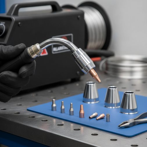
A loose contact tip, a clogged nozzle, or a shroud seated incorrectly can ruin an otherwise solid weld. Getting the tip and shroud set up properly takes only a few minutes, but it’s one of those details that separates clean, consistent welds from frustrating starts.
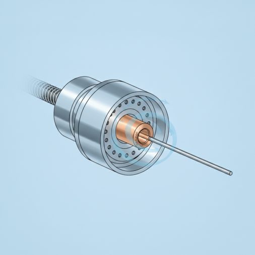
Proper MIG welding tip and shroud setup involves threading the correct contact tip size onto the tip holder finger-tight, seating the gas nozzle (shroud) firmly over the neck so it aligns concentrically, and setting the tip recess between flush and 2mm recessed for solid wire or slightly protruding for flux-core. The wire should extend 6–13mm (¼–½ inch) beyond the tip before you start welding.
Why the Contact Tip and Shroud Actually Matter
The contact tip is where electrical current transfers from the machine to the wire. If it’s worn, the wrong diameter, or not seated properly, arc stability suffers immediately. You’ll see erratic arc starts, increased spatter, and inconsistent wire feeding.
The shroud — also called the nozzle or gas cup — directs shielding gas around the arc. A poorly seated or damaged shroud means the gas coverage breaks down, leaving the weld puddle exposed to atmospheric contamination. The result is porosity, discoloration, and weak welds.
These two components work as a system. Neglecting either one affects the other’s performance.
Choosing the Right Contact Tip Size
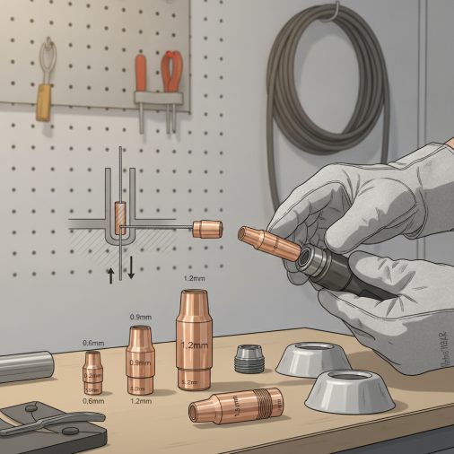
Contact tip diameter must match your wire diameter exactly. Using the wrong size is one of the most overlooked causes of poor wire feed and irregular arc.
Wire Diameter
Contact Tip Size
—
—
0.6 mm (0.023″)
0.6 mm tip
0.8 mm (0.030″)
0.8 mm tip
0.9 mm (0.035″)
0.9 mm tip
1.0 mm (0.040″)
1.0 mm tip
1.2 mm (0.045″)
1.2 mm tip
Some welders use a tip sized 0.1mm larger than the wire when feeding softer wires like aluminum or flux-core to reduce friction and burnbacks. For standard solid steel wire, always match tip to wire precisely.
not all MIG contact tips are interchangeable across machines — thread pitch, body diameter, and shank length vary between manufacturers. Always confirm compatibility before grabbing a tip from a different gun or brand.
Step-by-Step: Setting Up the Tip and Shroud
Follow this sequence every time you install or replace the contact tip and nozzle.
1. Turn off the welder and release wire tension.
Never work on the gun while the machine is energized. Feed out a short length of wire manually so it’s not under pressure against the tip.
2. Remove the nozzle (shroud) first.
Twist or pull it straight off depending on the type — threaded nozzles unscrew, slip-on nozzles pull free. Inspect for spatter buildup and carbon deposits inside.
3. Unscrew the old contact tip.
Use pliers if it’s seized. Worn tips will show a visible elongated hole at the wire exit point — that’s your cue it needs replacing regardless of hours used.
4. Thread in the new contact tip.
Hand-tighten only, then snug it down with pliers — roughly a quarter-turn past finger-tight. Over-tightening can seize the tip in the holder, making future removal difficult. Under-tightening causes arcing at the thread junction, which damages the tip holder.
5. Check the tip recess relative to the nozzle.
This is where most people skip an important detail. The correct tip position depends on the process:
– Solid wire (short circuit / spray): Tip flush with or recessed 1–2mm inside the nozzle
– Flux-core wire: Tip slightly protruding (1–2mm beyond nozzle end)
– Aluminum MIG: Tip flush to slightly protruding
Tip recess affects shielding gas coverage. A deeply recessed tip in a long nozzle creates a turbulence zone that can disturb gas flow.
6. Clean and reinstall the nozzle.
Apply anti-spatter spray or gel to the inside of the nozzle before reinstalling. This dramatically reduces spatter adhesion and makes future cleaning faster. Seat the nozzle firmly so it sits square on the gun neck — a crooked nozzle disrupts gas coverage.
7. Set the wire stick-out.
Trim the wire so it extends 6–10mm (¼–⅜ inch) for short circuit MIG on thin material, or up to 13mm (½ inch) for higher amperage work on thicker steel. proper MIG welder setup includes stick-out as a key variable that directly affects voltage at the arc.
Nozzle Types and When Each Applies
Not all shrouds are the same. The shape and material affect gas coverage, heat dissipation, and access in tight joints.
Nozzle Type
Best For
Notes
—
—
—
Cylindrical (straight)
General fabrication, flat welds
Most common; good gas coverage
Tapered (conical)
Tight joints, corner welds
Better access but reduced coverage
Recessed cup
High-spatter environments
Deeper gas pocket; protects tip longer
Copper
High-amperage applications
Better heat conductivity
Brass
Light to medium duty
Budget-friendly; adequate performance
In practice, most shop welders default to cylindrical copper nozzles for steel work. Tapered nozzles are genuinely useful when you’re working inside a box section or a corner joint where the standard nozzle physically won’t fit.
Common Tip and Shroud Problems — and How to Fix Them
Burnback (wire fusing to the tip)
Usually caused by wire stick-out that’s too short, travel speed that’s too slow, or a contact tip that’s too hot from extended use. Replace the tip, increase travel speed slightly, and check that your wire speed isn’t set too low for the voltage.
Excessive spatter on the nozzle
Often linked to incorrect shielding gas flow rate, wrong polarity, or a gas mixture that doesn’t suit the wire. reducing MIG welding spatter starts with dialing in gas coverage and wire feed speed together. Anti-spatter compound on the nozzle interior buys you more time between cleanings.
Poor arc starts or stuttering arc
Check the contact tip first. A worn tip with an oval exit hole causes the wire to make intermittent contact, producing a rough, unstable arc. Replace it before adjusting machine settings.
Gas coverage failure (porosity in the weld)
If the nozzle is seated off-center or has a large spatter blockage at the exit, shielding gas won’t flow evenly. Remove the nozzle, clean it thoroughly, and check that it seats square on reinstallation. Also verify your shielding gas flow rate is set correctly — typically 10–15 L/min for most shop conditions.
Wire feed grinding or resistance
If the wire feeds inconsistently, the contact tip bore may have worn oval or partially blocked with metal debris. Even a slightly worn tip adds resistance to wire travel, causing the drive rolls to work harder and the arc to fluctuate.
How Often to Replace Contact Tips
Contact tips are consumables. There’s no fixed hour-based replacement schedule, but these are reliable indicators:
– The exit hole is visibly oval rather than round
– The tip has discoloration or pitting along the bore
– Arc starts are inconsistent despite correct settings
– You’ve had one or more burnbacks through the tip
Heavy production welders typically swap tips every few hours of arc time. Hobby or occasional welders may get weeks from a single tip, depending on wire speed and material thickness.
Keep a small stock of tips in the correct size. Running out mid-project and continuing with a worn tip is one of the most common causes of frustrating, unexplained weld quality drops.
The Lincoln Electric Magnum Pro contact tips are a well-regarded option for machines like the Lincoln Weld-Pak series, with consistent bore tolerances that hold up well through extended use.
Anti-Spatter Products and Nozzle Maintenance
A simple anti-spatter spray applied to the nozzle interior before welding keeps it clear far longer between cleanings. Some welders prefer anti-spatter gel over spray — gel tends to stay in place better and doesn’t flash off as quickly under heat.
Clean the nozzle after every significant welding session. A nozzle cleaning tool or a flat-blade screwdriver works to scrape hardened spatter from the inside. Never weld through a partially blocked nozzle — restricted gas flow creates invisible porosity that weakens the joint.
FAQ
What does tip recess mean in MIG welding?
Tip recess refers to how far the contact tip sits inside the gas nozzle. A recessed tip sits 1–2mm below the nozzle opening, which is standard for solid wire MIG. A flush or slightly protruding tip position is more common with flux-core wire. The recess depth affects both gas coverage around the arc and protection of the tip from spatter.
Can I use any brand of contact tip in my MIG gun?
Not always. Contact tips vary in thread size, shank length, and body diameter between manufacturers and gun models. A tip from a Lincoln gun may not fit a Miller or Hobart gun without an adapter. Always match the tip to the gun manufacturer’s specification. When in doubt, reference the gun’s model number and order tips listed as compatible.
How tight should a MIG contact tip be?
Finger-tight plus roughly a quarter-turn with pliers. The tip should be snug enough that it doesn’t rattle or unscrew during welding, but not so tight that it seizes in the tip holder. Over-tightened tips are difficult to remove when hot and can damage the brass holder threads.
Why does my contact tip keep burning back?
Burnback typically happens when wire stick-out is too short, wire feed speed is too low for the voltage setting, or the tip is already worn and causing poor wire-to-tip contact. Check that the wire extends at least 6mm from the tip before striking the arc, and verify your wire speed and voltage are balanced. common MIG welding mistakes like incorrect wire speed are a frequent root cause of repeated burnbacks.
What’s the difference between a copper and brass MIG nozzle?
Copper nozzles handle heat better and are generally preferred for higher amperage work. Brass nozzles are less expensive and adequate for light to medium-duty welding. In practical terms, the difference matters more at sustained high amperage — for occasional or hobby use, brass performs adequately.
How do I know if my MIG shroud is the right size for my gun?
The shroud should seat firmly with no wobble and align concentrically over the contact tip. If it’s loose, off-center, or won’t seat fully, it’s the wrong size or design for your gun. Check the gun’s manufacturer part number for the correct nozzle specification. A poorly fitting nozzle is worse than a worn one because it disrupts gas coverage unpredictably.
Does tip recess change for different material thicknesses?
The recess setting is more about process and wire type than material thickness. However, when welding thicker material at higher amperages with spray transfer, a slightly deeper recessed tip can protect it from the more aggressive arc. For thin material on short circuit, flush to mildly recessed is the standard starting point.
Tip and shroud setup is quick to do right and expensive to ignore. A fresh contact tip matched to your wire diameter, a clean nozzle seated square, and the correct stick-out length will immediately improve arc consistency and reduce cleanup time. Check these components before troubleshooting settings on the machine — in most cases, the gun end is where the problem originates.