
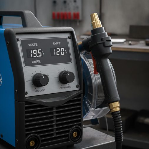
You’ve loaded flux-core wire, set the polarity, and now you’re staring at the voltage and wire-speed dials wondering where to start. Getting those numbers wrong means porosity, burn-through, or a cold, lumpy bead that won’t stick properly.
Gasless MIG welding settings depend primarily on wire diameter, material thickness, and your specific machine. As a general starting point, most hobbyist flux-core setups running 0.030 in (0.8 mm) wire on mild steel between 1/8 in and 3/16 in (3–5 mm) will operate somewhere in the 14–18 V range with wire-feed speeds roughly between 150–250 IPM, producing effective amperage in the range of 80–140 A. Thinner sheet requires lower voltage and slower wire speed; thicker material needs more of both. Always check your machine’s built-in settings chart first, then dial in from there.
Why Gasless MIG Settings Differ from Gas-Shielded MIG
Gasless MIG — properly called self-shielded flux-core arc welding (FCAW-S) — uses a tubular wire filled with flux compounds. When the arc melts the wire, those compounds generate their own shielding gas and slag layer. That chemistry changes how the arc behaves compared to standard solid-wire MIG with external shielding gas.
Self-shielded flux-core typically runs hotter and produces more spatter at equivalent wire-feed speeds. The arc voltage tends to be slightly lower than gas-shielded flux-core for the same wire size, and the process is more tolerant of drafty conditions. Understanding how gasless MIG welding works at a process level helps you interpret why the settings behave the way they do.
Polarity Matters Before You Touch the Dials
Self-shielded flux-core wire runs on DCEN — direct current electrode negative. This is the opposite of solid-wire MIG, which uses DCEP (electrode positive). If your polarity is wrong, the arc will be unstable, spatter will be excessive, and penetration will be poor regardless of how well your voltage and wire speed are set.
Most MIG machines require you to swap the torch and work-lead connections inside the wire-feed compartment to change polarity. Check your machine’s manual before striking an arc. For a deeper look at how polarity affects the weld, this explanation of MIG welding polarity covers the subject clearly.
The Relationship Between Voltage, Wire-Feed Speed, and Amperage
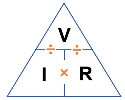
In MIG and flux-core welding, voltage and wire-feed speed (WFS) are the two dials you actually adjust. Amperage is not set directly — it is a result of the wire-feed speed. Feeding wire faster increases the current drawn by the arc.
Voltage controls arc length and bead profile. Higher voltage produces a flatter, wider bead with more fluidity. Too much voltage creates a flat, spatter-heavy puddle and can cause undercut. Too little voltage produces a narrow, convex, ropey bead that sits on top of the base metal rather than fusing into it.
Wire-feed speed controls heat input and deposition rate. If WFS is too high relative to voltage, the wire stubs into the puddle. If it’s too low, the arc becomes erratic and the bead is thin and cold. Voltage and wire-feed speed must be balanced together, not adjusted independently.
Starting Settings by Wire Diameter and Material Thickness
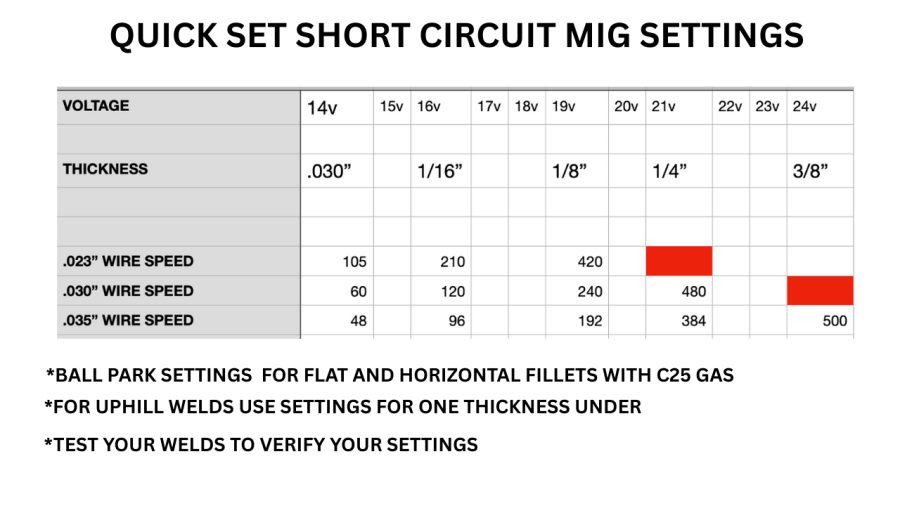
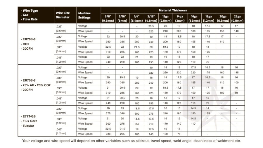
The table below gives practical starting-point ranges for common self-shielded flux-core wire sizes on mild steel. These are not manufacturer-certified specifications — treat them as a baseline to adjust from after running a test bead on scrap. Your machine, wire brand, and joint configuration will all influence the final numbers.
| Wire Diameter | Material Thickness | Voltage Range (approx.) | Wire-Feed Speed (approx.) | Approx. Amperage |
|---|---|---|---|---|
| 0.030 in (0.8 mm) | 18–14 gauge (1–2 mm) | 13–15 V | 120–175 IPM | 60–90 A |
| 0.030 in (0.8 mm) | 1/8 in (3 mm) | 15–17 V | 175–225 IPM | 90–120 A |
| 0.035 in (0.9 mm) | 1/8–3/16 in (3–5 mm) | 16–19 V | 175–275 IPM | 110–160 A |
| 0.035 in (0.9 mm) | 1/4 in (6 mm) | 18–21 V | 250–325 IPM | 150–200 A |
| 0.045 in (1.2 mm) | 3/16–3/8 in (5–10 mm) | 19–23 V | 200–350 IPM | 170–250 A |
These ranges represent typical hobbyist and light industrial usage on flat butt and fillet joints in the flat or horizontal position. Out-of-position welding — vertical or overhead — generally requires reducing voltage and wire-feed speed to keep the puddle manageable. A flux-core MIG welding settings chart with additional position and thickness breakdowns can help you refine these numbers further.
How to Use Your Machine’s Built-In Chart
Most flux-core capable MIG welders have a settings chart printed inside the wire-feed compartment door or in the owner’s manual. That chart is calibrated to the specific machine’s transformer or inverter characteristics and is always the best first reference point.
Find the row matching your wire diameter and base-metal thickness. Set both voltage and wire-feed speed to the middle of the suggested range. Run a test bead on a piece of clean scrap at the same thickness as your actual workpiece, then evaluate the result and make small adjustments from there.
Reading the Bead to Dial In Your Settings
A well-set flux-core bead on mild steel should be reasonably flat, consistent in width, and blend smoothly into the base metal on both toes. The slag should lift cleanly with a slag hammer after the weld cools. Moderate spatter is normal for self-shielded flux-core — it will always produce more spatter than gas-shielded MIG.
Use the bead appearance to guide adjustments. If your bead looks like one of the following, try the correction listed:
- Convex, ropey, or humped bead: Voltage is likely too low. Increase voltage in small steps.
- Very flat, wide, or undercut at the edges: Voltage is too high or travel speed is too slow. Reduce voltage or increase travel speed.
- Wire stubbing or arc cutting out: Wire-feed speed is too high relative to voltage. Reduce WFS or increase voltage slightly.
- Burn-through on thin material: Heat input is too high. Reduce voltage, reduce WFS, or increase travel speed.
- Cold lap or incomplete fusion: Heat input is too low or travel speed is too fast. Increase voltage or slow travel speed.
- Excessive spatter beyond normal: Polarity may be wrong, contact tip may be worn, or voltage is slightly low.
For a more complete look at what causes poor-looking or structurally weak welds, common MIG welding mistakes and their causes covers the most frequent errors and how to correct them.
Wire Diameter Selection and Machine Limits
Smaller-diameter wire — 0.030 in or 0.035 in — is better suited to thinner material and lower-amperage machines. Larger wire — 0.045 in — handles thicker plate but requires a machine capable of the higher current output. Trying to run heavy wire at the top of a machine’s output range pushes the duty cycle hard and may result in poor fusion.
Many 120 V flux-core machines marketed to hobbyists are limited to roughly 90–100 A continuous output. On these machines, 0.030 in or 0.035 in wire is typically the practical maximum, and material thicker than 3/16 in may require multiple passes or preheat rather than a single high-heat pass. The flux-core welding amperage chart page goes deeper on matching amperage output to material thickness.
Stick-Out Length and Its Effect on Settings
Contact-tip-to-work distance — commonly called stick-out — directly affects the arc. Self-shielded flux-core typically uses a longer stick-out than gas-shielded MIG, often in the range of 3/4 in to 1-1/4 in (19–32 mm), depending on wire size and the wire manufacturer’s recommendation.
Longer stick-out increases electrical resistance in the wire, which slightly softens the arc and reduces effective penetration. Shorter stick-out increases heat at the tip and can burn through the flux before it exits the nozzle. Keep stick-out consistent during welding and adjust it as a fine-tuning variable once voltage and WFS are roughly dialed in.
Travel Speed and Welding Position
Travel speed is the third variable that interacts with voltage and wire-feed speed. Slower travel speed increases heat input and bead width. Faster travel speed reduces heat input and produces a narrower bead.
When welding vertical-up with self-shielded flux-core, many operators reduce voltage by 1–2 V and wire-feed speed by 10–15% compared to flat-position settings to prevent the puddle from sagging. Vertical-down is generally not recommended for self-shielded flux-core on structural joints because it tends to produce cold-lap and incomplete fusion, particularly on thicker material.
Surface Preparation and Joint Fit-Up
Self-shielded flux-core is more tolerant of mill scale, light rust, and imperfect surfaces than solid-wire MIG — but that tolerance has limits. Heavy rust, paint, galvanizing, oil, and moisture all degrade arc stability and introduce porosity. Clean the joint area with a grinder or wire brush before welding.
Poor fit-up with gaps wider than the wire diameter causes burn-through and inconsistent penetration. For gaps that can’t be closed, reduce voltage and wire-feed speed and consider using a backing strip or running a root pass at lower heat before filling.
Safety Considerations
Self-shielded flux-core generates significantly more fume than gas-shielded MIG. The flux compounds produce metallic oxide fumes that require adequate ventilation. Use local exhaust ventilation or a welding fume extractor whenever possible, and position yourself to keep your head out of the fume plume.
Wear a welding helmet with at least a shade 10 lens, a welding jacket or flame-resistant clothing, and appropriate welding gloves. Keep flammable materials clear of the work area. Spatter from flux-core can travel further than solid-wire MIG, so check the surrounding area before starting. For a broader review of hazards, the risks associated with MIG welding applies equally to gasless flux-core work.
For structural, load-bearing, or regulated applications — including vehicle frames, trailers, pressure vessels, or lifting equipment — visual bead appearance alone cannot confirm weld quality or structural adequacy. These applications require a qualified welding procedure and appropriate inspection.
Frequently Asked Questions
What voltage should I use for 0.035 flux-core wire on 1/4 inch steel?
A common starting range for 0.035 in self-shielded flux-core wire on 1/4 in mild steel is approximately 18–21 V with wire-feed speed in the range of 250–325 IPM in the flat position. Always check your machine’s door chart first, run a test bead on scrap, and adjust based on bead profile and penetration.
Why is my gasless MIG weld producing so much spatter?
Some spatter is normal with self-shielded flux-core. Excessive spatter typically points to incorrect polarity (should be DCEN), voltage set too low relative to wire-feed speed, a worn or partially blocked contact tip, or wire that has picked up moisture. Check polarity first, then evaluate your voltage-to-WFS balance. Tips on reducing spatter in MIG welding cover practical corrective steps.
Can I run gasless flux-core wire on a standard MIG welder?
Most standard MIG welders support self-shielded flux-core wire, but you must switch to DCEN polarity by swapping the torch and work lead connections inside the machine, and you should remove or retract the gas nozzle to improve visibility. Confirm your machine accepts flux-core wire by checking the owner’s manual, as some entry-level machines are solid-wire only.
Does welding position change the voltage and wire-speed settings?
Yes. Flat and horizontal positions use the full setting range for a given thickness. Vertical-up welding generally requires reducing both voltage and wire-feed speed by roughly 10–15% to prevent the puddle from running. Overhead welding requires similar reductions. Vertical-down is generally avoided with self-shielded flux-core because it tends to produce cold-lap and poor fusion.
Is gasless flux-core suitable for thin sheet metal like car body panels?
Self-shielded flux-core is generally not the best choice for thin automotive sheet metal, typically below 18 gauge. The process runs hotter and produces more heat concentration than gas-shielded MIG, making burn-through and distortion on thin sheet difficult to control. For body panels, gas-shielded solid-wire MIG is a more controllable option.
What is a good contact-tip-to-work distance for gasless MIG?
Self-shielded flux-core typically uses a stick-out of 3/4 in to 1-1/4 in (approximately 19–32 mm), which is longer than gas-shielded MIG. The exact recommended distance depends on wire diameter and the wire manufacturer’s data sheet. Consistent stick-out throughout the weld helps maintain a stable arc and predictable penetration.
Getting Gasless MIG Settings Right the First Time
The most reliable starting point is always the settings chart inside your machine’s wire-feed compartment door. Match the wire diameter and material thickness, set both voltage and wire-feed speed to the middle of the suggested range, and evaluate the result on scrap before welding the actual part.
Polarity is the single most important pre-dial check — self-shielded flux-core must run on DCEN, and no amount of voltage adjustment will fix a polarity error. Once polarity is confirmed, balance voltage and wire-feed speed together rather than adjusting one in isolation.
For general fabrication and repair on mild steel, gasless flux-core is a capable and practical process. For anything structural, safety-critical, or regulated, use an approved welding procedure and arrange appropriate inspection rather than relying on bead appearance alone.


